


2-18
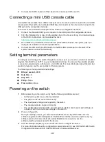
To remove a fan tray:
1.
Wear an ESD wrist strap and make sure it makes good skin contact and is reliably grounded.
2.
Grasp the handle of the fan tray with one hand and pull the fan tray part way out of the slot.
Support the fan tray bottom with the other and pull the fan tray completely out of the slot.
3.
Put the removed fan tray in an antistatic bag.
Figure2-18 Removing an LSWM1BFANSC fan tray
Installing/removing power supplies
WARNING!
•
To avoid bodily injury and device damage, strictly follow the procedures in
to install and remove a power supply.
•
Provide a separate circuit breaker for each power supply.
CAUTION:
Make sure each slot has a filler panel or module installed when the switch is operating.
The switch has four power supply slots. It is shipped with power supply slots PWR2 and PWR4
empty and power supplies slots PWR1 and PWR3 installed with filler panels.
The switch supports 2+1 and 2+2 power supply redundancy. You can install two to four power
supplies for the switch. For information about the power supplies available for the switch, see
H3C
S9820-64H Switch Hardware Information and Specifications
.
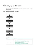
Figure2-19 Installation procedure
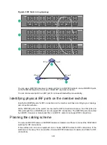
Figure2-20 Removal procedure
Install the power
supply
Connect the power
cord
Turn on the circuit
breaker
Turn off the circuit
breaker
Disconnect the power
cord
Remove the power
supply