background image


22 

For more information about the 

fan prefer-direction slot

 command, see 

H3C S5830 Switch Series 

Fundamentals Command Reference

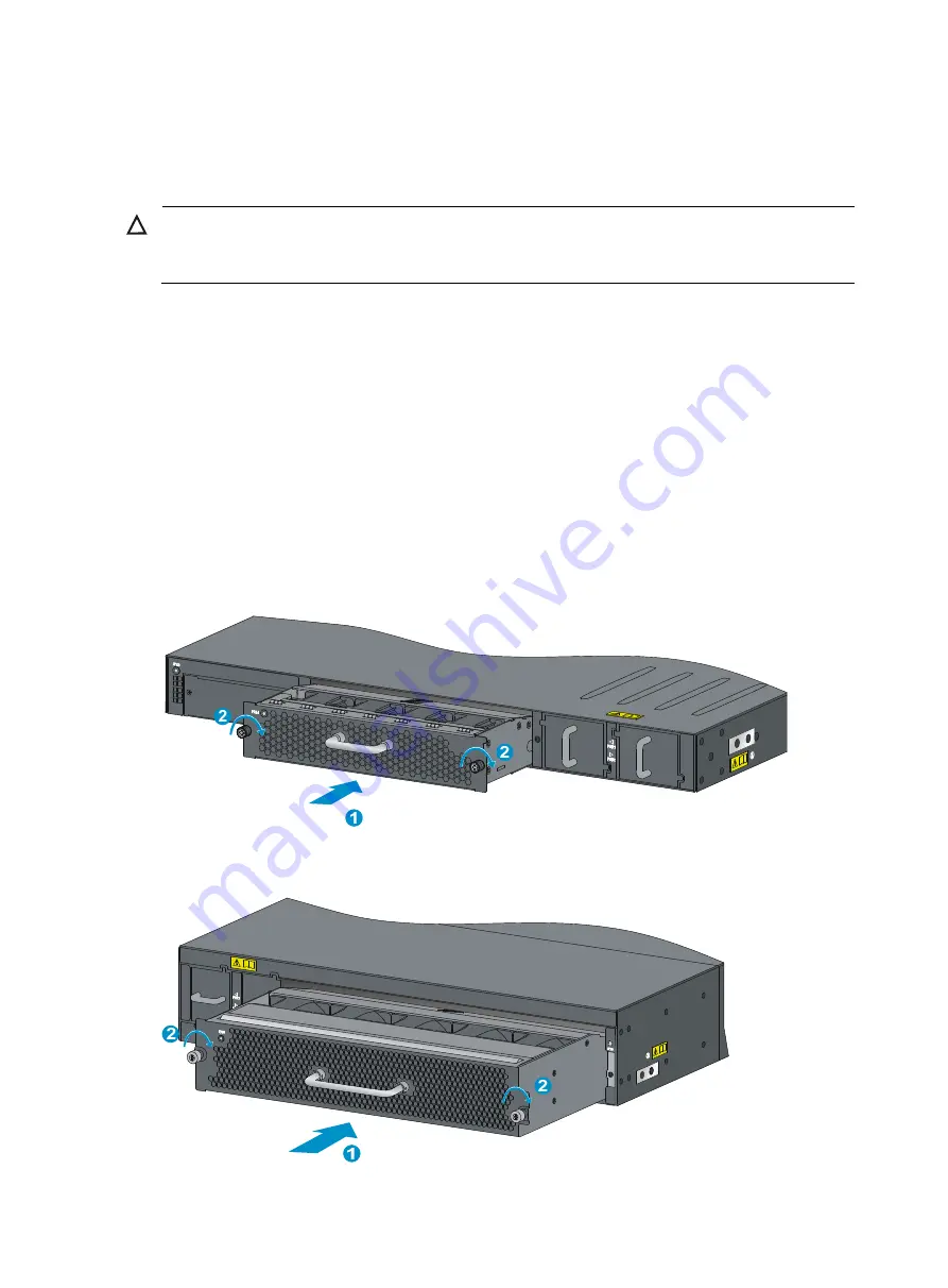
Installing a fan tray 


CAUTION: 

To prevent damage to the fan tray or the connectors on the backplane, insert the fan tray gently. If you 
encounter a hard resistance while inserting the fan tray, pull out the fan tray and insert it again.  


To install a fan tray: 

1.


Wear an ESD-preventive wrist strap and make sure it makes good skin contact and is well 
grounded. 

2.


Loosen the captive screws on the filler panel to remove the filler panel. 

3.


Unpack the fan tray and verify that the fan tray model is correct.  

4.


Grasp the handle of the fan tray with one hand and support the fan tray bottom with the other, and 
slide the fan tray along the guide rails into the slot until the fan tray seats in the slot and has a firm 

contact with the backplane (see callout 1 in 

Figure 27

 or 

Figure 28

). 

5.


Fasten the captive screw on the fan tray with a Philips screwdriver until the fan tray is securely fixed 
into the chassis (see callout 2 in 

Figure 27

 or 

Figure 28

). 

If the captive screw cannot be tightly attached, examine the installation of the fan tray. 

Figure 27


Installing an LSVM152SCFAN or LSVM252SCFAN fan tray 


Figure 28


Installing an LSVM1106SFAN or LSVM2106SFAN fan tray 


Содержание S5830 Series

Страница 1: ...H3C S5830 Switch Series Installation Guide New H3C Technologies Co Ltd http www h3c com hk Document version 6W103 20170526...

Страница 2: ...her trademarks that may be mentioned in this manual are the property of their respective owners Notice The information in this document is subject to change without notice Every effort has been made i...

Страница 3: ...xt represents commands and keywords that you enter literally as shown Italic Italic text represents arguments that you replace with actual values Square brackets enclose syntax choices keywords or arg...

Страница 4: ...ORTANT An alert that calls attention to essential information NOTE An alert that contains additional or supplementary information TIP An alert that provides helpful information Network topology icons...

Страница 5: ...screenshots and other information in the examples differ from what you have on your device Obtaining documentation To access the most up to date H3C product documentation go to the H3C website at htt...

Страница 6: ...tch 20 Grounding the switch with a grounding strip 20 Grounding the switch through the PE wire of an AC power cord 21 Installing removing a fan tray 21 Selecting a fan tray 21 Installing a fan tray 22...

Страница 7: ...1 Appendix A Technical specifications 43 Technical specifications 43 Cooling system 44 Cooling system of the S5830 52SC 44 Cooling system of the S5830 106S 45 Appendix B FRUs and compatibility matrixe...

Страница 8: ...2 10 100 1000Base T Ethernet port LED 3 ACT LED for the management Ethernet port 4 LINK LED for the management Ethernet port 5 Console port 6 Interface card status LED Slot 7 System status LED SYS 8...

Страница 9: ...interface card are installed Figure 3 S5830 52SC left side panel 1 Primary grounding point 2 Auxiliary grounding point S5830 106S panel views Figure 4 S5830 106S front panel 1 Management Ethernet por...

Страница 10: ...System status LED SYS NOTE The S5830 106S switch comes with one fan tray slot and two power modules slots with filler panels In this figure two LSVM1AC650 AC power modules and one LSVM1106SFAN fan tra...

Страница 11: ...ust be used indoors You can mount the switch in a rack but make sure Adequate clearance is reserved at the air inlet and exhaust vents for ventilation The rack has a good ventilation system Identify t...

Страница 12: ...gas limits in the equipment room Gas Maximum concentration mg m3 SO2 0 2 H2S 0 006 NH3 0 05 Cl2 0 01 EMI All electromagnetic interference EMI sources from outside or inside of the switch and applicati...

Страница 13: ...tch has power The laser light emitted from the optical fiber may hurt your eyes Installation tools Flat blade screwdriver P4 75mm Phillips screwdriver P1 100mm P2 150mm and P3 250mm ESD preventive wri...

Страница 14: ...le for any consequence caused thereby Figure 7 Hardware installation flow Start Install to a specified position Install a power module Install a fan tray Ground the switch Connect the power cord Verif...

Страница 15: ...ting bracket and cable management bracket kits for the H3C S5830 Switch Series Switch models Mounting brackets Cable management brackets Bracket view S5830 52SC One pair of 1U mounting brackets suppli...

Страница 16: ...pair of chassis rails and a pair of slide rails Figure 10 Chassis rail and slide rail kit for the S5830 52SC 1 Chassis rail 2 Slide rail For the S5830 52SC H3C provides slide rails of two sizes to in...

Страница 17: ...4 Installing an S5830 switch in the rack Mounting bracket position Installing the chassis rails and slide rails Installing the switch Rear mounting near the power modules Front mounting near the netwo...

Страница 18: ...mounting position near the network ports and one rear mounting position near the power modules and two grounding points one primary grounding point with a grounding sign and one auxiliary grounding p...

Страница 19: ...n the left side panel If you use either of the grounding points you must connect the grounding cable to the grounding point before you mount the switch in the rack To connect the grounding cable to a...

Страница 20: ...the primary grounding point fails or is not suitable for the installation site use the auxiliary grounding point Figure 16 Identifying the mounting and grounding positions 1 2 4 3 1 Rear mounting posi...

Страница 21: ...in the rack To connect the grounding cable to a chassis grounding point for example the primary grounding point 1 Select a grounding point 2 Unpack the grounding cable and the grounding screws You ca...

Страница 22: ...upplied in the mounting holes in the rack posts 3 Align the screw holes in one slide rail with the cage nuts in the rack post on one side and use screws user supplied to fix the slide rail to the rack...

Страница 23: ...hat the slide rails have been correctly attached to the rack posts see Attaching the slide rails to the rack 4 Install cage nuts user supplied to the front rack posts and make sure they are at the sam...

Страница 24: ...dentify the rack attachment position for the slide rails 2 Install cage nuts user supplied in the mounting holes in the rack posts 3 Align the screw holes in one slide rail with the cage nuts in the r...

Страница 25: ...nding cable for the S5830 106S 3 Verify that the slide rails have been correctly attached to the rack posts see Attaching the slide rails to the rack 4 Install cage nuts user supplied to the front rac...

Страница 26: ...tch in the rack I Figure 24 Installing the switch in the rack II IMPORTANT To ensure steadiness of the switch in the rack make sure the front ends of the slide rails reach out of the chassis rails as...

Страница 27: ...witch You can ground the switch in one of the following ways depending on the grounding conditions available at the installation site Grounding the switch with a grounding strip Grounding the switch t...

Страница 28: ...h generates alarms and the system LED flashes red or the switch may even be damaged Selecting a fan tray The S5830 switches provide two types of fan trays with different airflow directions from power...

Страница 29: ...the filler panel 3 Unpack the fan tray and verify that the fan tray model is correct 4 Grasp the handle of the fan tray with one hand and support the fan tray bottom with the other and slide the fan...

Страница 30: ...or the switches see Appendix B FRUs and compatibility matrixes Installing removing a power module Installing a power module CAUTION Follow the forward inertia of the power module when inserting it int...

Страница 31: ...well grounded 2 Remove the power cord from the power module When removing the DC power cord squeeze the tabs on the power cord connector with your thumb and forefinger and then pull the connector out...

Страница 32: ...rd 1 Press the tabs on the power cord connector with your thumb and forefinger 2 Pull the power cord connector out Figure 32 Removing the power module S5830 52SC 1 Pivot the latch to the right with yo...

Страница 33: ...the AC power cord supplied with the power module into the AC input power receptacle of the power module 2 Use a cable tie to secure the power cord to the handle of the power module as shown in Figure...

Страница 34: ...sion interface slot covered with a filler panel For the interface card available for the switch see Appendix B FRUs and compatibility matrixes Installing an interface card 1 Wear an ESD preventive wri...

Страница 35: ...f the interface card until all spring pressure is released 3 Pull the interface card along the guide rails until it completely comes out of the switch chassis If no new card is to be installed after y...

Страница 36: ...the switch with a console cable Figure 39 Setting up the configuration environment Connecting the console cable Console cable A console cable is an 8 core shielded cable with a crimped RJ 45 connecto...

Страница 37: ...terminal device to the switch as follows 1 Plug the DB 9 female connector to the serial port of the console terminal or PC 2 Connect the RJ 45 connector to the console port of the switch Setting termi...

Страница 38: ...serial port to be used from the Connect using list and click OK Figure 42 Setting the serial port used by the HyperTerminal connection 4 Set Bits per second to 9600 Data bits to 8 Parity to None Stop...

Страница 39: ...32 Figure 43 Setting the serial port parameters 5 Select File Properties in the HyperTerminal window Figure 44 HyperTerminal window 6 On the Settings tab set the emulation to VT100 and click OK...

Страница 40: ...have been set Power on the switch During the startup process you can access the BootWare menu to perform tasks such as software upgrade and file management The BootWare menu output and options differ...

Страница 41: ...etwork topology and high availability scalability and manageability IRF fabric setup flowchart Figure 46 IRF fabric setup flowchart Start Plan IRF fabric setup Install IRF member switches Connect the...

Страница 42: ...except the master switch automatically reboot and the IRF fabric is established Planning IRF fabric setup Planning IRF fabric size and the installation site Choose S5830 switch models and identify th...

Страница 43: ...y chain topology without interrupting network services You connect the IRF member switches through IRF ports the logical interfaces for the connections between IRF member switches Each IRF member swit...

Страница 44: ...interface card separately S5830 106S 10 fixed SFP ports on the front panel Planning the cabling scheme Use SFP cables or SFP transceivers and fibers to connect the IRF member switches If the IRF memb...

Страница 45: ...ft The following subsections describe several H3C recommended IRF connection schemes All these schemes use a ring topology IMPORTANT In these schemes all physical IRF ports are located on the same sid...

Страница 46: ...witch Series Fundamentals Configuration Guide to configure their member IDs member priorities and IRF port bindings Follow these guidelines when you configure the switches Assign the master switch hig...

Страница 47: ...ment station can reach each other 3 Use Telnet web or SNMP to access the IRF fabric from the network management station See H3C S5830 Switch Series Fundamentals Configuration Guide 4 Verify that you c...

Страница 48: ...can work properly the old power module has failed Contact the H3C local agent to replace the old power module Fan failure When a fan tray is operating properly its status LED is green If the LED is re...

Страница 49: ...display If terminal display is garbled verify that the following settings are configured for the terminal for example HyperTerminal Baud rate 9 600 Data bits 8 Parity None Stop bits 1 Flow control No...

Страница 50: ...r panel Power module slots 2 on the rear panel 2 on the rear panel Input voltage AC Rated voltage 100 VAC to 240 VAC 50 Hz or 60 Hz Rated voltage 100 VAC to 240 VAC 50 Hz or 60 Hz DC Rated voltage 40...

Страница 51: ...r flows in through the air vents in the fan tray panel and the power module panels circulates through the chassis and the power modules and exhausts at the port side as shown in Figure 53 When an LSVM...

Страница 52: ...830 106S When an LSVM1 106SFAN fan tray is used ambient air flows in through the air vents in the fan tray panel and the power module panels circulates through the chassis and the power modules and ex...

Страница 53: ...is with the LSVM1106SFAN fan tray 1 Power module air vents 2 Fan tray air vents 3 Port side air vents Figure 56 Airflow through the S5830 106S chassis with the LSVM2106SFAN fan tray 1 Power module air...

Страница 54: ...FAN No Yes LSVM2106SFAN No Yes Interface card options LSPM2SP2P Yes No Hot swappable power modules Every S5830 switch has two power module slots You can install one power module or for redundancy two...

Страница 55: ...Max output power 315 W S5830 52SC H3C LSVM1AC300 LSVM1DC300 Power Modules User Manual Hot swappable fan trays The S5830 switches use hot swappable fan trays for heat dissipation Table 12 describes the...

Страница 56: ...VM2106SFAN Fan Modules User Manual LSVM2106SFAN S5830 106S Fans Five 60 60 38 mm 2 36 2 36 1 50 in fans Fan speed 11000 R P M Max airflow 135 CFM Airflow direction Front to rear fans draw air from the...

Страница 57: ...t port You can connect this port to a PC or management station for loading and debugging system software or remote management Table 15 Management Ethernet port specifications Item Specification Connec...

Страница 58: ...s transceiver modules SFP GE SX MM850 A 850 nm LC 50 125 m multi mode optical fiber 62 5 125 m multi mode optical fiber 550 m 1804 46 ft over 50 125 m fiber 275 m 902 23 ft over 62 5 125 m fiber SFP G...

Страница 59: ...r 70 km 43 50 miles SFP GE LX SM1310 BIDI TX 1310 nm RX 1490 nm LC 9 125 m single mode optical fiber 10 km 6 21 miles SFP GE LX SM1490 BIDI TX 1490 nm RX 1310 nm LC 9 125 m single mode optical fiber 1...

Страница 60: ...rnet ports numbered 47 and 48 on the S5830 52SC form two combo interfaces Ports 49 and 47 form one combo interface and ports 50 and 48 form another Only one port in a combo interface can work at a tim...

Страница 61: ...e optical fiber 70 km 43 50 miles SFP GE LH70 SM1530 CW 1530 nm LC 9 125 m single mode optical fiber 70 km 43 50 miles SFP GE LH70 SM1550 CW 1550 nm LC 9 125 m single mode optical fiber 70 km 43 50 mi...

Страница 62: ...ft LSTM1STK N A N A SFP cable 5 m 16 40 ft LSTM2STK N A N A SFP cable 7 m 22 97 ft For the SFP transceiver module specifications see H3C Low End Series Ethernet Switches Pluggable Modules Manual NOTE...

Страница 63: ...ashing red An alarm is generated Off The switch is powered off 10 100 1000Base T Ethernet port LED Each 10 100 1000Base T auto sensing Ethernet port has a status LED to show port operating status and...

Страница 64: ...r receiving data Off No link is present on the port Management Ethernet port LEDs Every S5830 switch has two management Ethernet port LEDs LINK and ACT Table 24 Management Ethernet port LED descriptio...

Страница 65: ...swappable fan trays 48 Hot swappable power modules 47 I Installation tools 6 Installing the switch in a 19 inch rack 8 Installing removing a fan tray 21 Installing removing a power module 23 Installi...

Отзывы: