


4-5
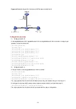
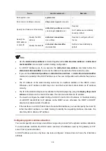
Figure 4-3
Network diagram for IP addressing configuration
Configuration procedure
# Assign a primary IP address and a secondary IP address to VLAN-interface 1.
<Switch> system-view
[Switch] interface vlan-interface 1
[Switch-Vlan-interface1] ip address 172.16.1.1 255.255.255.0
[Switch-Vlan-interface1] ip address 172.16.2.1 255.255.255.0 sub
# Set the gateway address to 172.16.1.1 on the PCs attached to subnet 172.16.1.0/24, and to
172.16.2.1 on the PCs attached to subnet 172.16.2.0/24.
# Ping a host on subnet 172.16.1.0/24 from the switch to check the connectivity.
<Switch> ping 172.16.1.2
PING 172.16.1.2: 56 data bytes, press CTRL_C to break
Reply from 172.16.1.2: bytes=56 Sequence=1 ttl=255 time=25 ms
Reply from 172.16.1.2: bytes=56 Sequence=2 ttl=255 time=27 ms
Reply from 172.16.1.2: bytes=56 Sequence=3 ttl=255 time=26 ms
Reply from 172.16.1.2: bytes=56 Sequence=4 ttl=255 time=26 ms
Reply from 172.16.1.2: bytes=56 Sequence=5 ttl=255 time=26 ms
--- 172.16.1.2 ping statistics ---
5 packet(s) transmitted
5 packet(s) received
0.00% packet loss
round-trip min/avg/max = 25/26/27 ms
The output information shows that the switch can communicate with the hosts on subnet
172.16.1.0/24.
# Ping a host on subnet 172.16.2.0/24 from the switch to check the connectivity.
<Switch> ping 172.16.2.2
PING 172.16.2.2: 56 data bytes, press CTRL_C to break
Reply from 172.16.2.2: bytes=56 Sequence=1 ttl=255 time=25 ms
Reply from 172.16.2.2: bytes=56 Sequence=2 ttl=255 time=26 ms
Reply from 172.16.2.2: bytes=56 Sequence=3 ttl=255 time=26 ms