23
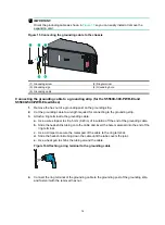
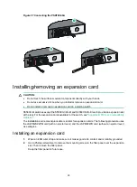
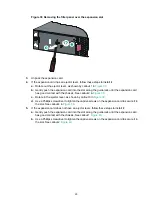
Figure 29 Removing the power module
Connecting the power cord
Table 5 Power source options and power cord connection procedures for the power
modules
Power module model
Power source option
Power cord connection procedure
Fixed power module
AC power source
Connecting the power cord for the built-in AC
power module
–48 VDC power source in
the equipment room or an
RPS (RPS800-A or
RPS1600-A)
Connecting a power cord for the built-in DC power
module
PSR150-A1/PSR150-A2
AC power source
Connecting the PSR150-A1/PSR150-A2
PSR150-D1
–48 VDC power source in
the equipment room or an
RPS (RPS800-A or
RPS1600-A)
Connecting the PSR150-D1/PSR560-56D
PSR560-56D
–48 VDC power source in
the equipment room or an
RPS (RPS1600-A)
Connecting the PSR150-D1/PSR560-56D
PSR360-56A/PSR720-56
A/PSR1110-56A
AC power source
Connecting the
PSR360-56A/PSR720-56A/PSR1110-56A
CAUTION:
•
The AC power cord provided with the PSR150-A1/PSR150-A2 power module uses a C13
connector. The AC power cord provided with the PSR360-56A/PSR720-56A/PSR1110-56A
power module uses a high-temperature C15 connector. Do not mix them.
•
Provide a circuit breaker for each power module and make sure the circuit breaker is off before
installation.


