background image


20 

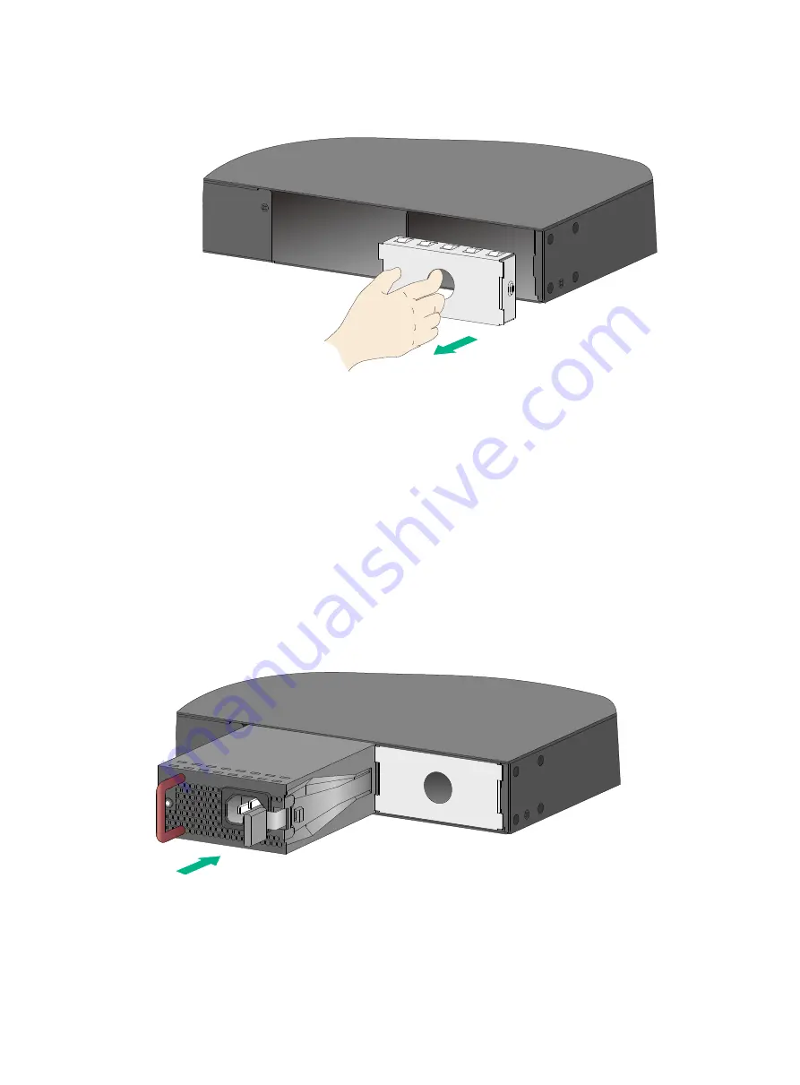
Figure 27 Removing the filler panel 


3. 

Unpack the power module and verify that the power module model is correct. 
Put away the packaging box and packaging bag of the power module for future use. 

4. 

Correctly orient the power module with the power module slot (use the letters on the power 
module faceplate for orientation), grasp the handle of the power module with one hand and 
support its bottom with the other, and slide the power module slowly along the guide rails into 
the slot until you hear that the latch of the power module clicks into the slot. 
When you insert the power module into the slot, you can do that through slight inertia so that the 
terminals of the power module can have a good contact with the backplane. 
The PSR1110-56A power module adds 64 mm (2.52 in) to the depth of the switch, as shown 
in 

Figure 29

5. 

Install the filler panel over the empty power module slot to prevent dust and ensure good 
ventilation if you install only one power module. 

Figure 28 Installing a power module 


Содержание S5150-EI Series

Страница 1: ...H3C S5150 EI Switch Series Installation Guide Hangzhou H3C Technologies Co Ltd http www h3c com Document version 5W100 20160415...

Страница 2: ...ll other trademarks that may be mentioned in this manual are the property of their respective owners Notice The information in this document is subject to change without notice Every effort has been m...

Страница 3: ...ions Convention Description Boldface Bold text represents commands and keywords that you enter literally as shown Italic Italic text represents arguments that you replace with actual values Square bra...

Страница 4: ...TE An alert that contains additional or supplementary information TIP An alert that provides helpful information Network topology icons Convention Description Represents a generic network device such...

Страница 5: ...he appearance and specifications of H3C transceiver modules H3C SFP SFP XFP Transceiver Modules and Network Cables Installation Guide Guides you through installing SFP SFP XFP transceiver modules and...

Страница 6: ...tallation software upgrading and software feature configuration and maintenance documentation Products Solutions Provides information about products and technologies as well as solutions Software Down...

Страница 7: ...56A power module 21 Connecting the power cord 22 Connecting an AC power cord to the switch 22 Connecting a DC power cord to the switch 23 Connecting the PSR150 A1 24 Connecting the PSR150 D1 25 Conne...

Страница 8: ...port 50 Management Ethernet port 50 USB port 50 1 10GBASE T autosensing Ethernet port 51 2 5G 1000 100BASE T autosensing Ethernet port 51 SFP port 51 LEDs 54 System status LED 54 Power module status...

Страница 9: ...n the required range To avoid electrical shocks do not open the chassis while the switch is operating To avoid damage caused by improper operation do not open the chassis even if the switch is powered...

Страница 10: ...e humidity is low In the worst case electrostatic adsorption can cause communication failure Table 1 Dust concentration limit in the equipment room Substance Concentration limit particles m Dust 3 x 1...

Страница 11: ...elded interface cables when necessary Laser safety WARNING The switch is Class 1 laser device Do not stare into any fiber port when the switch has power The laser light emitted from the optical fiber...

Страница 12: ...N Keep the tamper proof seal on a mounting screw on the chassis cover intact and if you want to open the chassis contact H3C for permission Otherwise H3C shall not be liable for any consequence Figure...

Страница 13: ...front and rear mounting brackets Install the front mounting brackets at the port side or power module side Install the rear mounting brackets according to the rack depth If the rack depth is in the r...

Страница 14: ...Hole for attaching the bracket to a rack 2 Hole for attaching the bracket to the switch chassis Figure 5 Rear mounting bracket and load bearing screw 1 Hole for attaching the bracket to a rack 2 Load...

Страница 15: ...side power module side or middle installation position for the S5150X 16S EI Port side or power module side for the S5150X 16ST EI Middle installation position for the S5150 24S PWR EI c Use M4 screws...

Страница 16: ...a One person supports the chassis bottom with one hand holds the front part of the chassis with the other hand and pushes the chassis into the rack gently b The other person uses M6 screws and cage n...

Страница 17: ...to the S5150 24S PWR EI switch You can install the front mounting brackets at the port side or power side mounting position as needed The following takes port side mounting as an example The power si...

Страница 18: ...ting bracket to the chassis e Unpack the load bearing screws f Install the load bearing screws Attach the load bearing screw to one of the two installation positions as red marked in Figure 12 Figure...

Страница 19: ...with the wide flange outside the rack 4 Mount the switch chassis in the rack a One person supports the chassis bottom with one hand holds the front part of the chassis with the other hand and pushes t...

Страница 20: ...rack posts and attaches the front mounting brackets with M6 screws user supplied to the front rack posts Make sure the front and rear mounting brackets have securely attached the switch to the rack F...

Страница 21: ...feet to the four round holes in the chassis bottom 4 Place the switch with upside up on the workbench Grounding the switch WARNING Correctly connecting the switch grounding cable is crucial to lightni...

Страница 22: ...chassis 1 Remove the grounding screw from the rear panel of the switch chassis 2 Use the grounding screw to attach the ring terminal of the grounding cable to the grounding screw hole Figure 17 Connec...

Страница 23: ...re 19 Connecting the grounding cable to a grounding strip 1 Grounding post 2 Grounding strip 3 Grounding cable 4 Hex nut Connecting the grounding cable to a grounding strip S5150X 16S EI and S5150X 16...

Страница 24: ...ckness must be a minimum of 3 5 mm 0 14 in Weld the yellow green grounding cable to the angel iron or steel tube and treat the joint for corrosion protection Figure 21 Grounding the switch by burying...

Страница 25: ...antee the grounding effect ground the switch by connecting the grounding cable provided with the switch to the grounding strip in the equipment room Installing removing a power module WARNING In power...

Страница 26: ...se a flathead screwdriver to remove the filler panel Figure 25 Removing the filler panel 3 Unpack the power module and verify that the power module model is correct 4 Correctly orient the power module...

Страница 27: ...nel to prevent dust and ensure good ventilation if no power module is installed in the slot Installing a PSR360 56A PSR720 56A PSR1110 56A power module CAUTION To prevent damage to the power module or...

Страница 28: ...h the other and slide the power module slowly along the guide rails into the slot until you hear that the latch of the power module clicks into the slot When you insert the power module into the slot...

Страница 29: ...ower module along the guide rails until it is part way out 4 Grasp the handle of the power module with one hand support the bottom with the other hand and pull the power module slowly along the guide...

Страница 30: ...ower module RPS800 A or RPS1600 A Connecting the PSR150 D1 S5150 24S PWR EI PSR360 56A PSR720 56A PSR1110 56A Connecting the PSR360 56A PSR720 56A PSR1110 56A Connecting an AC power cord to the switch...

Страница 31: ...cord is to be connected to the receptacle 3 Correctly orient the plug at one end of the cable with the power receptacle on the power module and insert the plug into the power receptacle See callout 1...

Страница 32: ...into the two holes next to the power receptacle on the power module and pull the bail latch leftwards see Figure 35 3 Connect one end of the AC power cord supplied with the power module to the power r...

Страница 33: ...C power cord correctly orient the plug at one end of the cable with the power receptacle on the power module and insert the plug into the power receptacle see callout 1 in Figure 37 The power receptac...

Страница 34: ...f the power module see callout 2 and callout 3 in Figure 38 4 Connect the other end of the AC power cord to an AC power outlet Figure 38 Connecting the PSR720 56A Verifying the installation After you...

Страница 35: ...ole port takes effect if you connect both the serial console port and mini USB console port Figure 39 Connecting the console port to a PC Connecting the console cable A console cable is an 8 core shie...

Страница 36: ...onnector at one end to connect to the mini USB console port of the switch and a standard USB Type A connector at the other end to connect to the USB port on the PC To connect to the PC through the min...

Страница 37: ...29 Figure 41 Device Driver Installation Wizard 6 Click Continue Anyway if the following dialog box appears Figure 42 Software Installation 7 Click Finish...

Страница 38: ...equired terminal settings Bits per second 9 600 Data bits 8 Parity None Stop bits 1 Flow control None Powering on the switch Before powering on the switch verify that the following conditions are met...

Страница 39: ...oftware matching release notes for the device After the startup completes you can access the CLI to configure the switch For more information about the configuration commands and CLI see H3C S5150 EI...

Страница 40: ...eability IRF fabric setup flowchart Figure 44 IRF fabric setup flowchart To set up an IRF fabric Step Description 1 Plan IRF fabric setup Plan the installation site and IRF fabric setup parameters Pla...

Страница 41: ...ric equals the total switching capacities of all member switches Plan the installation site depending on your network solution as follows Place all IRF member switches in one rack for centralized high...

Страница 42: ...sical port to it When connecting two neighboring IRF member switches you must connect the physical ports of IRF port 1 on one switch to the physical ports of IRF port 2 on the other switch The S5150 E...

Страница 43: ...g the cabling scheme Use twisted pair cables SFP network cables or SFP transceiver modules and fibers to connect the IRF member switches If the IRF member switches are far away from one another choose...

Страница 44: ...s in a ToR solution You can install IRF member switches in different racks side by side to deploy a top of rack ToR solution Figure 49 shows an example for connecting 9 top of rack IRF member switches...

Страница 45: ...SFP transceiver modules and fibers to connect the IRF member switches as planned Wear an ESD wrist strap when you connect SFP network cables or SFP transceiver modules and fibers For how to connect t...

Страница 46: ...problems configure a minimum of one multi active detection MAD mechanism to detect the presence of multiple identical IRF fabrics and handle collisions For more information about MAD detection see H3...

Страница 47: ...problem a Verify that the AC power cord is securely connected to the switch and the AC input power receptacle on the switch and the connected AC power outlet are in good condition b Verify that the ex...

Страница 48: ...witch and the connected AC power outlet are in good condition b Verify that the external AC power system is operating correctly c If the problem persists contact H3C Support Symptom 3 The system statu...

Страница 49: ...is correct the configuration terminal displays booting information when the switch is powered on If the setup is incorrect the configuration terminal displays nothing or garbled text No display Sympt...

Страница 50: ...6 USB port 7 Mini USB console port 8 Serial console port 9 Management Ethernet port 10 SFP port Figure 51 S5150X 16S EI rear panel 1 Grounding screw 2 Power module slot 1 3 Power module slot 2 NOTE T...

Страница 51: ...us LED RPS 4 System status LED SYS 5 Management Ethernet port status LED MGMT 6 USB port 7 Mini USB console port 8 Serial console port 9 Management Ethernet port 10 SFP port 11 1 10GBASE T autosensing...

Страница 52: ...hing button 9 Mini USB console port 10 Serial console port 11 Power module 2 status LED PWR2 12 SFP port Figure 55 S5150 24S PWR EI rear panel 1 Grounding screw 2 Power module slot 1 3 Power module sl...

Страница 53: ...range 48 VDC to 60 VDC Max voltage range 36 VDC to 72 VDC NOTE You can use the site 48 VDC power source or an H3C RPS800 A or RPS1600 A RPS as the DC power source AC input Rated voltage range 100 VAC...

Страница 54: ...the rear panel Input voltage PSR360 56A PSR720 56A AC input Rated voltage range 100 VAC to 240 VAC 50 Hz or 60 Hz Max voltage range 90 VAC to 264 VAC 47 Hz to 63 Hz PSR1110 56A AC input Rated voltage...

Страница 55: ...ax PoE power capacity per port Two PSR1110 56A 720 W 30 W One PSR1110 56A and one PSR720 56A 720 W 30 W One PSR1110 56A and one PSR360 56A 720 W 30 W Two PSR720 56A 720 W 30 W One PSR1110 56A 720 W 30...

Страница 56: ...e S5150X 16S EI switch The switch supports mix of an AC power module and a DC power module You can install one power module or two power modules for redundancy on the S5150 24S PWR EI switch The PoE c...

Страница 57: ...t power 720 W H3C PSR720 56A Power Module User Manual PSR1110 56A Rated input voltage range 115 VAC to 240 VAC 50 Hz or 60 Hz Max input voltage range 102 5 VAC to 264 VAC 47 Hz to 63 Hz Max output pow...

Страница 58: ...24S PWR EI provide a management Ethernet port status LED on the front panel You can connect the management Ethernet port to a PC or management station for loading and debugging software or remote mana...

Страница 59: ...24S PWR EI switch provides 2 5G 1000 100BASE T autosensing Ethernet ports Table 16 2 5G 1000 100BASE T autosensing Ethernet port specifications Item Specification Connector type RJ 45 Interface attrib...

Страница 60: ...46 ft 400 500 m 1640 42 ft Multi mode 62 5 125 200 275 m 902 23 ft 160 200 m 656 17 ft SFP GE LX SM131 0 A 1310 LC Single mode 9 125 N A 10 km 6 21 miles Multi mode 50 125 500 or 400 550 m 1804 46 ft...

Страница 61: ...SFP ports Cable description Cable length LSWM1STK 0 65 m 2 13 ft LSWM2STK 1 2 m 3 94 ft LSWM3STK 3 m 9 84 ft LSTM1STK 5 m 16 40 ft Figure 56 SFP network cable 1 Connector 2 Pull latch NOTE As a best p...

Страница 62: ...erating correctly Flashing green 1 Hz The switch is performing power on self test POST Steady red The switch has failed the POST or is faulty Flashing yellow 1 Hz Some ports have failed to pass POST o...

Страница 63: ...t status LEDs the S5150 24S PWR EI switch provides a port mode LED The port mode LED indicates the type of information that the network port LEDs are showing Table 24 Port mode LED description LED mar...

Страница 64: ...s present on the port The port is operating in PoE mode for PoE switches only 2 5G 1000 100BASE T autosensing Ethernet port LED The S5150 24S PWR EI switch provides a status LED for each 2 5G 1000 100...

Страница 65: ...us LEDs on the switch indicate the IRF member IDs of the switch For example if the LED for port 5 is steady green and the other port LEDs are off the IRF member ID of the switch is 5 SFP port LED Tabl...

Страница 66: ...lation site for the switch Figure 57 Airflow through the S5150X 16S EI switch chassis 1 Air inlets 2 Power module air vents 3 Built in fan air vents Figure 58 Airflow through the S5150 24S PWR EI swit...

Страница 67: ...59 Figure 59 Airflow through the S5150X 16ST EI switch 1 Air inlets 2 Built in fan air vents 1 2...

Страница 68: ...tch 27 troubleshooting configuration terminal problems 41 verify the IRF fabric setup 37 39 connecting AC power cord 22 console cable 27 DC power cord 23 first time switch access 27 IRF member switche...

Страница 69: ...itch through AC power cord 16 switch with a grounding conductor buried in the earth ground 16 switch with grounding strip 14 H hardware 1 10G BASE T autosensing Ethernet port LED 56 1 10GBASE T autose...

Страница 70: ...autosensing Ethernet port 56 2 5G 1000 100 BASE T autosensing Ethernet port 56 management Ethernet port 55 port mode 55 power module status 54 RPS status 55 SFP port 57 system status 54 technical spe...

Страница 71: ...ing IRF member IDs 33 planning IRF topology 34 rack mounting by using front and rear mounting brackets on 19 inch rack 9 rack mounting by using front mounting brackets on 19 inch rack 6 removing PPSR3...

Страница 72: ...dministration troubleshooting configuration terminal problems 41 troubleshooting fan failure 41 troubleshooting fixed power module failure 39 troubleshooting hot swappable power module failure 40 trou...

Страница 73: ...65 mounting switch 13...

Отзывы: