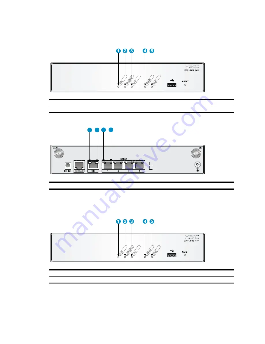
background image


31 

MSR 930-GU 

Figure 36


Front panel LEDs 


(1) System status LED (SYS) 

(2) Network status LED (INTERNET) 

(3) VPN status LED (VPN)

(4) 3G status LED (WWAN) 

(5) Received 3G signal strength indication LED (RSSI) 


Figure 37


Rear panel LEDs 


(1) GE port status LED (yellow) 

(2) GE port status LED (green) 


MSR 930-GT 

Figure 38


Front panel LEDs 


(1) System status LED (SYS) 

(2) Network status LED (INTERNET)

(3) VPN status LED (VPN)

(4) 3G status LED (WWAN) 

(5) Received 3G signal strength indication LED (RSSI) 


1

2

1

2

Содержание MSR 930

Страница 1: ...H3C MSR 930 Routers Installation Guide Hangzhou H3C Technologies Co Ltd http www h3c com Document version 6W100 20130301...

Страница 2: ...ll other trademarks that may be mentioned in this manual are the property of their respective owners Notice The information in this document is subject to change without notice Every effort has been m...

Страница 3: ...tton names are inside angle brackets For example click OK Window names menu items data table and field names are inside square brackets For example pop up the New User window Multi level menus are sep...

Страница 4: ...V5 Describe software features and configuration procedures MSR router series command references V5 Provide a quick reference to all available commands MSR router series Web based configuration guide...

Страница 5: ...Technical support service h3c com http www h3c com Documentation feedback You can e mail your comments about product documentation to info h3c com We appreciate your comments...

Страница 6: ...le and setting terminal parameters 14 Setting console terminal parameters 15 Connecting the power adapter 18 Verifying the installation 18 Powering on the router 18 Startup process 19 Power on check 2...

Страница 7: ...MSR 930 DG 27 MSR 930 SA 28 Technical specifications 28 Antenna specifications 29 Appendix B LEDs 30 LEDs 30 MSR 930 30 MSR 930 GU 31 MSR 930 GT 31 MSR 930 DG 32 MSR 930 SA 33 LED description 33 Index...

Страница 8: ...can cause permanent eye damage Use a good grounding system This is essential for reliable operation Confirm that the resistance between the chassis and the ground is less than 1 ohm Site requirements...

Страница 9: ...preventive plug into the ESD preventive socket in the chassis 4 Attach the alligator to the chassis IMPORTANT Check the resistance of the ESD preventive wrist strap for safety The resistance reading...

Страница 10: ...intake and exhaust vents for heat dissipation The installation site ventilation system is adequate Temperature 0 C to 40 C 32 F to 104 F Relative humidity 5 to 90 noncondensing Cleanness Dust concent...

Страница 11: ...l signal cable Optional Electricity safety Install a UPS In case of emergency during operation switch off the external power switch Workbench The workbench is stable The workbench is grounded properly...

Страница 12: ...eal on a mounting screw on the chassis cover intact and if you want to open the chassis contact H3C for permission Otherwise H3C shall not be liable for any consequence Installation prerequisites You...

Страница 13: ...6 Figure 1 Installation flowchart Installing the router When installing the router...

Страница 14: ...face downwards and the sides with ventilation openings are perpendicular to the ground as shown in Figure 3 To mount the router on a wall 1 Mark the locations of the two mounting holes on the wall wi...

Страница 15: ...rounding conductor The router provides only a ring terminal but no grounding cable Purchase a grounding cable if necessary Attaching the ring terminal 1 Cut the grounding cable as appropriate for conn...

Страница 16: ...e ring terminal Grounding the router with a grounding strip 1 Remove the grounding screw from the router chassis 2 Put the ring terminal of the grounding cable on the grounding screw 3 Use a screwdriv...

Страница 17: ...re 6 Grounding to a conductor buried in the earth Installing a SIM card 1 Use a screwdriver to loosen the screws of the SIM card socket cover on the bottom of the chassis and remove the cover Figure 7...

Страница 18: ...sten the screws on the cover Figure 9 Installing the cover CAUTION To avoid damage to the holder use proper strength when you install the SIM card Do not insert the SIM card into the holder without pu...

Страница 19: ...h the antenna to the router as shown in Figure 11 Avoid over tightening The antenna must be vertical to the ground to achieve the optimal signal receiving Figure 11 Installing a 3G antenna On a dual 3...

Страница 20: ...the male connector to the bracket 2 Adjust the angle of the antenna to 180 3 Attach the antenna to the male connector of the cable 4 Attach the female connector of the cable to the router Figure 14 I...

Страница 21: ...onnect the cable to the port of the CSU DSU 3 Examine the LINK LED status For more information see LED description Figure 16 Connecting a serial port cable Connecting the console cable and setting ter...

Страница 22: ...ng the console cable Setting console terminal parameters To set console terminal parameters 1 Select Start All Programs Accessories Communications HyperTerminal The Connection Description dialog box a...

Страница 23: ...he HyperTerminal connection 4 Set Bits per second to 9600 Data bits to 8 Parity to None Stop bits to 1 and Flow control to None and click OK NOTE To restore the default settings click Restore Defaults...

Страница 24: ...ect File Properties in the HyperTerminal window Figure 21 HyperTerminal window 6 On the Settings tab set the emulation to VT100 or Auto Detect and click OK Figure 22 Setting the terminal emulation par...

Страница 25: ...stallation verify that There is enough space around the router for heat dissipation The router is mounted securely on the wall or on a sturdy workbench Antennas USB devices and interface modules are i...

Страница 26: ...yright c 2004 2012 Hangzhou H3C Technologies Co Ltd Compiled Date Aug 19 2012 CPU Type P1010 CPU L1 Cache 32KB CPU L2 Cache 256KB CPU Clock Speed 533MHz Memory Type DDR3 SDRAM Memory Size 256MB Memory...

Страница 27: ...displays information correctly You can see the startup window on the local console terminal For more information see Startup process After completing the POST the system prompts you to press Enter Wh...

Страница 28: ...es agent System configuration problems If the configuration environment setup is correct the console terminal displays boot information when the router is powered on If the setup is incorrect the cons...

Страница 29: ...authentication mode password Sysname ui console0 set authentication password simple 123456 When you set the password by using the set authentication password cipher simple password command note the f...

Страница 30: ...panel indicate abnormal state of the SIM card and 3G antenna verify the following items The SIM card has been correctly installed and makes good contact with the card socket The SIM card matches the...

Страница 31: ...an reboot the router by pressing the Reset button for a short time or power off the router If you have saved some configurations you can use the CLI to delete the configuration file Then you can press...

Страница 32: ...0 GU MSR 930 GT MSR 930 DG and MSR 930 SA Chassis views The figures in this appendix are for illustration only MSR 930 Figure 24 MSR 930 front view 1 USB port 2 Reset button Figure 25 MSR 930 rear vie...

Страница 33: ...27 MSR 930 GU rear view 1 3G antenna main connector MAIN 2 Power adapter port 3 Console AUX port 4 Ethernet WAN port GE0 5 Ethernet LAN ports GE1 to GE4 6 3G antenna auxiliary connector DIV 7 Groundi...

Страница 34: ...nector MAIN 7 Grounding screw MSR 930 DG Figure 30 MSR 930 DG front view 1 3G antenna auxiliary connector DIV1 2 USB port 3 Reset button 4 3G antenna main connector MAIN1 Figure 31 MSR 930 DG rear vie...

Страница 35: ...0 3 Ethernet LAN ports GE1 to GE4 4 Grounding screw 5 Power adapter port 6 Console AUX port Technical specifications Item 930 930 GU 930 GT 930 DG 930 SA Console port 1 USB port 1 GE WAN port 1 GE LAN...

Страница 36: ...ated input voltage 100 VAC to 240 VAC 50 Hz or 60 Hz Max AC power 24 W Operating temperature 0 C to 40 C 32 F to 104 F Relative humidity non condensing 5 to 90 Antenna specifications Item Specificatio...

Страница 37: ...x B LEDs LEDs MSR 930 Figure 34 Front panel LEDs 1 System status LED SYS 2 Network status LED INTERNET 3 VPN status LED VPN Figure 35 Rear panel LEDs 1 GE port status LED yellow 2 GE port status LED g...

Страница 38: ...D WWAN 5 Received 3G signal strength indication LED RSSI Figure 37 Rear panel LEDs 1 GE port status LED yellow 2 GE port status LED green MSR 930 GT Figure 38 Front panel LEDs 1 System status LED SYS...

Страница 39: ...green MSR 930 DG Figure 40 Front panel LEDs 1 System status LED SYS 2 Network status LED INTERNET 3 VPN status LED VPN 4 3G status LED WWAN 5 Received 3G signal strength indication LED RSSI Figure 41...

Страница 40: ...dy green The SDRAM is performing self test Flashing green 8 Hz The system software image is being copied and decompressed Flashing green 1 Hz Comware has started with the configuration file and the ro...

Страница 41: ...to the wireless network and is operating in 2G mode Flashing yellow 8 Hz Data is being received or transmitted The router is operating in 2G mode RSSI Front panel Off Weak or no signal Steady green S...

Страница 42: ...tools 3 Installing the router 6 L LED description 33 LEDs 30 P Password loss 22 Power supply failure 21 Powering on the router 18 Pre installation checklist 3 R Restoring the factory settings 23 S Saf...

Отзывы: