


13
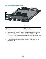
Figure 6
Interface card appearance
(1) Captive screw
(2) Ejector lever
4.
Gently push the interface card in along the guide rails until the
interface card is in close contact with the switch (see callout 1
in
Figure 7
). Then push the ejector levers at both sides inward (see
callout 2 in
Figure 7
).
5.
Fasten the captive screws with a Philips screwdriver to fix the
interface card.


