


21
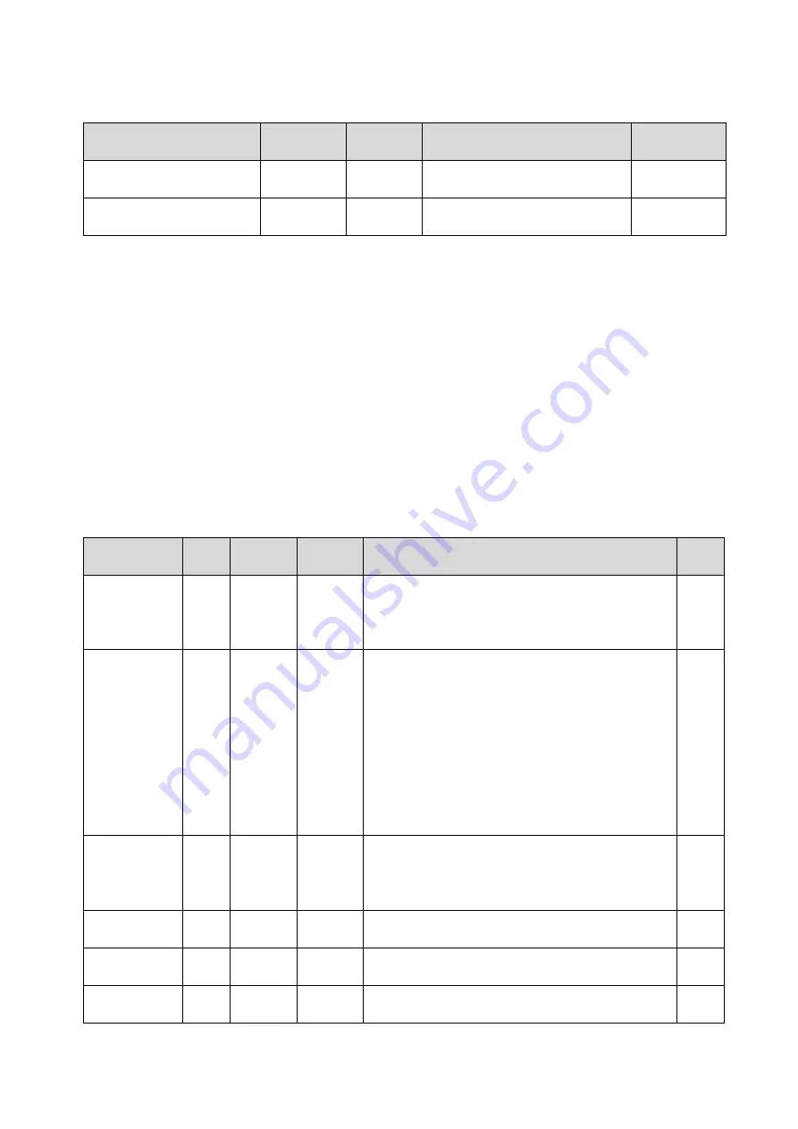
Then there is possible to change relay status by Modbus communication protocol command by
requested value writing to following addresses:
Function
Address
[hex]
X
Address
[dec]
X
Description
Status
Far condition for Relay1
0x0042
66
0 ... Relay1 open
1 ... Relay1 closed
R/W
Far condition for Relay2
0x0043
67
0 ... Relay2 open
1 ... Relay2 closed
R/W
6.1.5. Output relay alarm condition configuration with using of Modbus
communication protocol
With Modbus communication protocol there is possible to set regulator’s parameters described at
at page 10. Follow next steps:
1) To address 0x0044 (68) write value1 – it enables Modbus setting. By the way it blocks
regulator’s keyboard – local keyboard is blocked during remote control setting change.
2) Write the desired settings / changes to the addresses from 0x0045 (69) to 0x004E (78). New
setting can be done simultaneously or each register can be written alone
3) To address 0x004F (79) write value 1. Once this step is done, new setting is physically stored
into device memory (confirm change). Then registers 0x004F (79) and 0x0044 (68) are
automatically cleared (zero). It automatically unlocks the keyboard too.
Whole setting process can be cancelled by writing value 0 to address 0x0044 (68). At this time no
changes are stored and last setting stays valid.
Function
Unit
Address
[hex]
X
Address
[dec]
X
Description
Status
Modbus
Remote
Control
[-]
0x0044
68
0 ... disable
1 ... enable (for this time device’s keyboard is
blocked, if key is pressed, message BLOC
is shown)
R/W
Value
assigned to
output
Relay1
by
value
0x0045
69
0 ... Off
1 ... temperature
2 ... relative humidity
3 ... atmospheric pressure
4 ... computed value
5 ... binary input 1
6 ... binary input 2
7 ... binary input 3
8 ... Far condition 0
9 ... Far condition 1
R/W
When close
Relay1
[-]
0x0046
70
0 ... alarm occurs, when measured value is
LOWER than preset alarm value
1 ... alarm occurs, when measured value is
HIGHER than preset alarm value
R/W
Alarm value
for Relay1
by
value
0x0047
71
preset alarm value (threshold)
R/W
Delay for
Relay1
[sec] 0x0048
72
Time in seconds Time in seconds that the
condition must be valid to evaluate alarm
R/W
Hysteresis
of Relay1
by
value
0x0049
73
Value wihch must be set back below / above
a given threshold in order to open the relay
R/W