background image

l


20

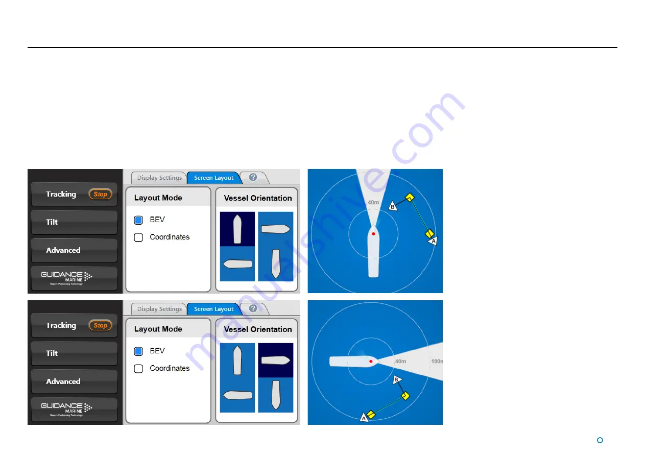
Vessel Orientation

CyScan Dashboard supports four different layouts of the Bird’s Eye View so that the 
operator can choose the one which best represents their surroundings.
For instance, if the operator is facing forward when using the Dashboard, they may want 
the bow of the vessel in the BEV to point upwards, so that targets located on the starboard 
side of the vessel are shown on the right-hand side of the BEV.

To set Vessel Orientation:

1. Navigate to Advanced > Display Options > Screen Layout.
2. Click on the vessel outline that points in the required direction.

Содержание CyScan AS

Страница 1: ...rator s Guide Guidance Marine Ltd 5 Tiber Way Meridian Business Park Leicester LE19 1QP UK T 44116 229 2600 E sales guidance eu com www guidance eu com www marine direct W A R R A N T Y See our standa...

Страница 2: ...er and may not be used sold transferred copied or reproduced in whole or in part in any manner or form or in or on any media to any person other than in accordance with the terms of the Owner s Agreem...

Страница 3: ...Introduction to Single and Multi Target Tracking 29 To Start Tracking 29 To Stop Tracking 29 Positional Display Modes 31 Bow and Starboard Axes 32 A and B Axes A Pos and B Pos 32 Selecting Targets fo...

Страница 4: ...Target Types 51 Targets Installation and Position 52 Low Temperature Operation 53 Using the On Screen Keyboard 54 Working with Alarms 55 Filtering Alarms 55 Using the Historic Alarm List 56 Network Co...

Страница 5: ...l 5 Introduction This section contains the following pages Welcome page 6 System Overview page 7 CyScan Sensor Part Names page 8...

Страница 6: ...perform the various tasks necessary to operate the system and use it for tracking These include Tracking Basics see page 21 and Single and Multi Target Tracking see page 27 Support Information see pag...

Страница 7: ...is provides the DP operator with status information and control of the system and the data stream being fed to the DP system The CyScan Service Interface is used for system installation and maintenanc...

Страница 8: ...t Names The diagram below illustrates various parts of the sensor unit and gives the terms used for them Client Data Power DP Feed Optical Window Rotor Base Plate Sensor Information Display Access Pla...

Страница 9: ...Shut Down page 10 Screen Layout page 11 Tracking Information Quality page 18 Display Settings page 19 Vessel Orientation page 20 You may also find the following sections of the Appendices useful at t...

Страница 10: ...1 Click on the Guidance button in the lower left corner of the screen This will reveal buttons in the side bar as follows see right Suspend Places the sensor into a sleep mode The rotor ceases spinni...

Страница 11: ...l 11 Screen Layout The CyScan Dashboard screen is split into three distinct sections these are 1 Main Screen and Bird s Eye View BEV see page 12 2 Side Bar see page 14 3 Menu Pane see page 16 1 2 3...

Страница 12: ...ing zone can be adjusted using the Drag Handles to suit different situations See Dynamic Blanking Zones on page 22 Range Circles The Range Circles act as a visual guide to show the distance between th...

Страница 13: ...he DP format selected and which coordinate system is being used to display the positional information see Positional Display Modes on page 31 Zoom Control Click on the left hand side of the control ma...

Страница 14: ...EV contains control and display components in addition to the coordinates pane After pressing the Guidance button Toggle Coordinate Type Signal Quality Coordinate Data DP Message Format Current Tilt M...

Страница 15: ...BEV and Coordinates Layout Mode F5 Toggles between enlarged and standard sized reflections F6 Toggles between the day view and night view F7 Toggles between the About System pane and the full main sc...

Страница 16: ...foot of the Side Bar are pressed which causes the Bird s Eye View BEV to contract towards the top of the screen Clicking the same button for a second time causes the Menu Pane to disappear and the BE...

Страница 17: ...ing ends the layout automatically reverts to Bird s Eye View As long as Coordinates View remains selected the main screen will again display coordinates once the next tracking operation commences To S...

Страница 18: ...flections from the intended targets and to ignore any unwanted reflections Before tracking has been selected the Data Quality and Coordinates area in the upper left corner of the screen is empty Once...

Страница 19: ...n Brightness control To change day night mode and adjust brightness 1 Navigate to Advanced Display Options Display Settings 2 Click on one of the Day Night Mode symbols 3 Click on the left side of the...

Страница 20: ...nstance if the operator is facing forward when using the Dashboard they may want the bow of the vessel in the BEV to point upwards so that targets located on the starboard side of the vessel are shown...

Страница 21: ...l 21 Tracking Basics This section contains the following pages Dynamic blanking zones page 22 Working with Reflections page 23 Scanner Tilt Controls page 25...

Страница 22: ...Installers Guide Setting the Dynamic Blanking Zone The start and end of the zone can be set to any positions around the circle to the nearest degree subject to the minimum and maximum sizes of the zo...

Страница 23: ...or displayed on the BEV This mechanism is useful when unwanted reflections cannot be eliminated by means of the dynamic blanking zone function alone It can be used at any time even during tracking Ran...

Страница 24: ...hows the horizontal width of each target measured in degrees Lower Middle and Upper These columns indicate whether the scanner is pointing low or high in relation to the detected reflections This can...

Страница 25: ...o manually tilt the optics to reach the target For example when station keeping close to a platform where the targets are mounted high up and the CyScan optics must be tilted up at them See Manually T...

Страница 26: ...the buttons to adjust the angle The adjacent list of estimated elevation angles for visible targets helps you to arrive at the best leveller angle 2 Click on the Apply button to confirm your changes...

Страница 27: ...does it form the basis of a contract Implementation of the material covered in this section will vary according to the type of DP system used in conjunction with the CyScan system The use of or relian...

Страница 28: ...ology When a CyScan AS sensor is used in conjunction with an AS prism the system can uniquely identify the AS prism target from all the clutter of other reflective objects in the scene No other laser...

Страница 29: ...be calculated Note Multi Target tracking assumes that all the reflectors are attached to the same rigid body e g rig if the selected targets are not all mounted on the same structure it will violate...

Страница 30: ...ng the Edit process the existing tracking will continue to work Any Edits made by the user can be cancelled by pressing Cancel We only allow additional targets to be tracked if the Quality of the exis...

Страница 31: ...axes on page 32 Range Bearing Range and Bearing mode displays the distance and the bearing of the primary or only target from the sensor The radial markers around the outside of the BEV are zeroed in...

Страница 32: ...lable for multi target tracking In this mode the position of the sensor vessel is expressed in metres from the target along A and B axes which have their origin at the primary target The axes are init...

Страница 33: ...you select target 1 becomes the primary target which forms the origin of the A and B coordinate axes The second reflection that you select target 2 sets the default orientation of the A and B coordina...

Страница 34: ...e secondary sets the default direction of the A axis Any additional targets targets 3 9 will provide additional redundancy to the tracking Axis A runs from the primary target to the secondary Axis B i...

Страница 35: ...towards the CyScan vessel on the display The right most reflection is selected as target 1 and the left most reflection as target 2 Axis A runs from right to left on the display Axis B is drawn 90 cl...

Страница 36: ...Heading Key the required heading value into the numerical entry box and click Preview Alternatively move the red compass needle to the required position either by clicking and dragging it or by repea...

Страница 37: ...yScan Ethernet Dashboard Monitoring Mode page 38 CyScan Ethernet Dashboard In Command Mode see page 39 Note that a CyScan system running with Serial communications supports only a single Dashboard and...

Страница 38: ...ng mode the controls relating to the Dashboard itself will be active but those relating to the CyScan sensor will be disabled A Monitoring Dashboard displays the same reflections and positional data a...

Страница 39: ...cating that the system is suspended The same message is displayed if a Dashboard is opened whilst the sensor is suspended See Start Up and Shut Down on page 10 In this state clicking the Resume button...

Страница 40: ...nformation This section contains the following pages Serial Numbers and Software Versions page 41 DP Feed page 42 Manual Power Control page 43 Ethernet Sensor Data Logging page 44 Serial Sensor Data L...

Страница 41: ...or These numbers identify the hardware configuration and product revision and will be requested by Guidance Marine in the event of an application service or support call to the company Product Label T...

Страница 42: ...be done from the Dashboard in order to change the CyScan DP settings use the CyScan Service Interface see document 94 0559 CyScan AS Installer s Guide which also contains descriptions of the availabl...

Страница 43: ...g button on the side bar 2 Click on the Reflections tab if not already in focus 3 Click on the Manual Control tick box in the Power Control panel To Use Manual Power Control 1 Adjust the power level b...

Страница 44: ...most recent data logs can be exported to a removable drive on the Dashboard computer To Export Data Logs 1 Insert a USB or other removable drive into the Dashboard computer 2 Navigate to Advanced Data...

Страница 45: ...f available USB drives 5 Click on Export Data Logs Either before or during the export operation the Refresh button can be used to update the Available Space field Alternative Export Methods Exporting...

Страница 46: ...ot resolve the issue please contact the system installer or equipment provider who are trained to assist with installation and operational problems If the problem cannot be resolved by the system inst...

Страница 47: ...the system unit Ensure that there are no errors displayed Otherwise power cycle the unit and observe the messages on the display Check for ice build up under the rotor Remove any ice which may be pre...

Страница 48: ...ree cloth with IPA spray to carefully wipe the optical window If the material on the window is difficult to remove warm soapy water with a non abrasive cloth may be used to clear the window To clean t...

Страница 49: ...he insert releases and can be pulled out Reverse the above procedure to replace the fuse Both fuses have the same specification Live Neutral Ensure the replacement fuse has the same specification as t...

Страница 50: ...get Types page 51 Targets Installation and Position page 52 Low Temperature Operation page 53 Using the On Screen Keyboard page 54 Working with Alarms page 55 Network Communication Settings page 57 Cy...

Страница 51: ...ended range operations Variable configurations allow for optimisation of the visible reflection visible reflection level or reflected power A fixed layout rugged version includes a robust housing brig...

Страница 52: ...ve positions can be automatically surveyed by the system Installation Tips The targets should ideally be mounted at the same height as the sensor while the vessel is within the expected working area C...

Страница 53: ...l remain blank and the rotor will not rotate until the internal temperature of the base unit rises above 15 C When the system is not in use i e un powered or suspended the sensor should be protected b...

Страница 54: ...nabled Otherwise click F11 or the Enable On Screen Keyboard button in the Dashboard Hotkeys menu To use the on screen keyboard Simply click on any text entry field and the OSK will pop up ready for us...

Страница 55: ...ty and current state of an alarm are reflected in its colour and shape Information grey symbols Warning orange symbols Error red symbols Fatal red symbols The arrowhead symbol indicates that an alarm...

Страница 56: ...o Advanced Alarms and ensure that the Current Alarms tab is in focus 2 Select the alarms that you wish to move into the Historic list To accept one alarm Click on the required entry and click on the b...

Страница 57: ...but IS possible from the CSI Network Config tab Sensor on board network configuration section see document 94 0363 4 CyScan Installer s Guide To View the Network Comms Settings 1 Click on the Advanced...

Страница 58: ...5 for 5 second wave period Environmental Operating Temperature Range Min 25 C Max 55 C Ingress Protection Rating IP66 rated Standards Compliance EN60945 IEC60825 EMC Certification CE Certified FCC Par...

Страница 59: ...ta Logging Ethernet 43 Serial 44 DP Feed 8 30 41 E E mail 43 Data Logs 43 F Fuse Information 48 H Hotkeys 15 L Labels 40 Low Temperature Operation 52 M Manually Tilting the Scanner 26 Manual Power Con...

Страница 60: ...Axes 30 Sub zero Temperatures 52 Suspended 10 38 System Logging 43 System Specifications 57 T Target AS Prism 50 AS Target 28 Cylindrical 50 Installation 54 55 Installation Tips 51 Non AS Target 28 Po...

Страница 61: ...l 61 Document History Document Number Changes Issue Date 94 0560 A First release of CyScan AS Operator s Guide 25 10 2017 94 0560 B Corrections and Align Heading had been added 22 02 2018...

Страница 62: ......

Отзывы: