background image

Gate Operator Class Categories ------------------------------------------------------------inside cover
Units and Standards Conversion Chart ---------------------------------------------------inside cover

PLEASE READ THIS FIRST! --------------------------------------------------

page iii

Important Safety Instructions  --------------------------------------------------

page 1


Disconnecting the Operator -----------------------------------------------------------page 


Important Safety Instructions for the Consumer ------------------------------------page 2


Secondary Means of Protection Against Entrapment ------------------------------page 5


Required Safety Precautions for Gates -----------------------------------------------page 6


Warning Signs and Labels -------------------------------------------------------------page 7

Installation  --------------------------------------------------------------------------

page 8


Parts List ---------------------------------------------------------------------------------page 8


Technical Specifications    -------------------------------------------------------------page 0


Installation Overview  ------------------------------------------------------------------page 


Installation of the Mounting Hardware ----------------------------------------------page 2


Mounting the Operator -----------------------------------------------------------------page 6


Installation of the Closed Position Stop ---------------------------------------------page 6


Mounting the Control Box -------------------------------------------------------------page 7


Connecting the Power Cable  ---------------------------------------------------------page 8


Powering the System  --------------------------------------------------------------

page 19


Solar Chart -------------------------------------------------------------------------------page 9


Connecting the Transformer -----------------------------------------------------------page 9

Control Board Settings   ----------------------------------------------------------

page 22


DIP Switches ----------------------------------------------------------------------------page 22


Setting the Closed Position ------------------------------------------------------------page 23


Obstruction Sensitivity -----------------------------------------------------------------page 24


Setting Your Personal Transmitter Code   -------------------------------------

page 25

Installing the Receiver   -----------------------------------------------------------

page 26

Connecting Additional Safety Devices   ----------------------------------------

page 27

Connecting Accessories   ----------------------------------------------------------

page 29

Push to Open Installation  --------------------------------------------------------

page 31

Maintenance & Troubleshooting Guide   --------------------------------------

page 33

Repair Service   ---------------------------------------------------------------------

page 36

Accessory Catalog   ----------------------------------------------------------------

page 37

 Table of Contents


KEEP THESE INSTRUCTIONS FOR FUTURE REFERENCE

Содержание SW-2000XL

Страница 1: ...of this product releasing GTO Inc from any and all liability If you are not in agreement with this disclaimer or do not feel capable of properly following all installation and safety instructions you may return this product for full replacement value READ ALL INSTRUCTIONS CAREFULLY AND COMPLETELY before attempting to install and use this automatic gate operator This gate operator produces a high l...

Страница 2: ...access locations not servicing the general public in which unauthorized access is prevented via supervision by security personnel The GTO PRO 2000XL Gate Operator is intended for use with vehicular swing gates The operator can be used in Class I Class II Class III and Class IV applications FOR YOUR RECORDS Please record the product serial number located on the right hand side of the control box an...

Страница 3: ...ng Hardware page 12 Mounting the Operator page 16 Installation of the Closed Position Stop page 16 Mounting the Control Box page 17 Connecting the Power Cable page 18 Powering the System page 19 Solar Chart page 19 Connecting the Transformer page 19 Control Board Settings page 22 DIP Switches page 22 Setting the Closed Position page 23 Obstruction Sensitivity page 24 Setting Your Personal Transmit...

Страница 4: ... and other access control products These optional accessories see the enclosed GTO PRO Accessory Catalog are available The GTO PRO 2000XL Operator features adjustable obstruction sensing This safety feature makes the gate stop and reverse direction within 2 seconds when it comes in contact with an obstruction MIN is the factory setting meaning the gate will exert the minimum force on an obstructio...

Страница 5: ...ons and warnings in this manual are identified with this warning symbol The symbol identifies conditions that can result in damage to the operator or its components serious injury or death Because GTO automatic gate operators are only part of the total gate operating system it is the responsibility of the consumer to ensure that the total system is safe for its intended use Disconnecting the Opera...

Страница 6: ...erator is proper for the type and size of gate its frequency of use and the proper class rating 2 Make sure the gate has been properly installed and swings freely in both directions Repair or replace all worn or damaged gate hardware prior to installation A freely moving gate will require less force to operate and will enhance the performance of the operator and safety devices used with the system...

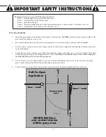
Страница 7: ...s access to it 2 Be careful with moving parts and avoid close proximity to areas where fingers or hands could be pinched 3 Devices such as contact sensors safety edges and non contact sensors photo beams provide additional protection against entrapment 4 If push buttons or key switches are installed they should be within sight of the gate yet located at least 10 feet from any moving part of the ga...

Страница 8: ...ay to it at least once per month 7 Service the gate and gate operator regularly Grease hinges spray push pull tube with high quality silicone spray and replace the battery every 3 5 years 8 To operate this equipment safely YOU must know how to disconnect the operator for manual gate operation see page 1 If you have read the instructions and still do not understand how to disconnect the operator co...

Страница 9: ...ent The GTO PRO 2000XL utilizes Type A an inherent i e built in entrapment sensing system as the primary type of entrapment protection Also the GTO PRO 2000XL has provisions for the connection of Type B2 protection to be used as the secondary type of entrapment protection if desired 1 For gate operators utilizing a contact sensor e g safety edge sensor Type B2 in accordance with UL 325 51 8 4 i A ...

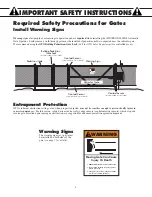
Страница 10: ...signs alert people of automatic gate operation and are required when installing the GTO PRO 2000XL Automatic Gate Operator Furthermore a walk through gate must be installed if pedestrian traffic is expected near the vehicular gate We recommend using the GTO Bulldog Pedestrian Gate Lock Call the GTO Sales Department for controlled access 1 KEEP CLEAR Gate may move at any time 2 Do not allow childre...

Страница 11: ...L SERIES GTO Inc Tallahassee Florida USA Disconnect operator ONLY when the control box power switch is OFF and the gate is NOT moving LISTED US C Product identification and manual operation instruction label 1 installed on right hand side of control box Logo and warning labels 2 installed on each side of operator housing 1 KEEP CLEAR Gate may move at any time 2 Do not allow children to operate gat...

Страница 12: ...ZW f 1ZSdWa W f 0 Zb f 0 Zb f 0 Zb f 0 Zb gZ 1OPZS BWS EOaVS QY EOaVS EOaVS cb cb 6O ReO S 5ObS S Ob e eS 1OPZS 5ObS 0 OQYSb ab Wd b 0 OQYSb 1cab S Ac b 1O R ab 0 OQYSb 1Z aSR aWbW Ab ZObS SQSWdS c bW U AQ Se E Z GATE OPENER 0caVW Ua f 0 Zb EOaVS f 0caVW U QY cb f 1ZSdWa W ...

Страница 13: ...be needed to run from the transformer to the control box length depends upon the distance between the transformer power supply and the control box See Powering the System on page 19 and the Accessory Catalog PVC conduit If your gate is more than 1000 away from an ac power source you will need to use at least 5 watts of solar charging power to trickle charge the battery See the Accessory Catalog If...

Страница 14: ...r tuned to 318 MHz Operator length with push pull tube fully retracted is 33 mounting point to mounting point Max stroke is 13 Adjustable auto close timer OFF to 120 s and obstruction sensitivity Power terminal bock accommodates a transformer and solar panels DIP switches simplify setup of gate operator Accessory terminal block fully compatible with push button controls digital keypads safety loop...

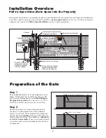
Страница 15: ...t Installation Overview Pull to Open Gates Gate Opens into the Property The diagram shown below is an example of a pull to open installation on a chain link fence and single gate Furthermore if you have a push to open gate you will need to purchase a push to open bracket see Accessory Catalog to properly configure your system See Push to Open Installation on page 31 before proceeding Horizontal Cr...

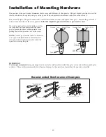
Страница 16: ...nt the thrust of the operator from pulling the bolts and washers out of the wood NOTE A fence post smaller than 6 in diameter or 6 square should be made of metal instead of wood so that it will remain stable while the operator is moving the gate Post Bracket Post Pivot Bracket Metal Plate Wooden Post Post Bracket Post Pivot Bracket Metal Plate Wooden Post Recommended Reinforcement Examples Thin Wa...

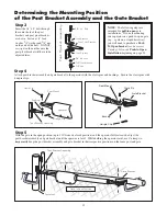
Страница 17: ...ertighten the nut because the post pivot bracket will have to be adjusted later Step 4 Attach post bracket assembly and gate bracket to the operator with the clevis pins and bushings Secure the clevis pins with hairpin clips 3 8 x 2 Bolt 3 8 Nut Post Pivot Bracket Post Bracket Post Bracket 3 8 Lock Washer Post Bracket Assembly 3 8 Washer NOTE The following steps are intended for pull to open gate ...

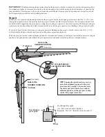
Страница 18: ...tant clearances With the post pivot bracket in the optimum position for clearance and freedom of movement reattach the operator to the gate bracket in the open position and recheck the gate operator level and make sure the brackets are clamped securely IMPORTANT While determining the mounting point for the post pivot bracket assembly be sure that the position allows for minimum 2 inches of clearan...

Страница 19: ...age bolts longer than 8 not supplied must be used Step 10 Mark reference points for bolt holes on the gate cross member through middle of gate bracket slots Drill 3 8 holes into the gate cross member as marked Mount gate bracket using 2 3 8 x 3 bolts washers lock washers and nuts provided Cut off excess bolt length extending beyond the tightened nuts Gate Bracket Mounting Examples c R BcPS 1VOW W ...

Страница 20: ...front mount and close the gate remember to support operator Fasten the closed position stop plate to the end of the gate frame on the gate centerline but do not tighten it completely Slide the stop plate toward the fence post until they touch see illustration Once you have moved the stop plate to the correct position tighten its hardware completely Use the appropriate hardware for your type of gat...

Страница 21: ...cure mounting method The control box must be mounted at least 3 feet above the ground to protect it from rain splash snow etc and at least 3 feet from an AC power source to prevent electrical interference Use mounting holes and screws provided to mount control box to a secure surface 1Z aSR aWbW Ab ZObS 5ObS 7 1Z aSR aWbW C L NOTE The battery that came with your GTO PRO 2000XL MUST be placed in th...

Страница 22: ...le Sealing Nut Hub Lock Nut Strain Relief Step 1 Make sure the control box power switch is in the OFF position The ON OFF Switch is located on the bottom of the control box Remove the control box cover and slide the battery into position with its terminals to the RIGHT see illustration Connect the BLACK battery wire to the NEGATIVE battery terminal Connect the RED battery wire to the POSITIVE term...

Страница 23: ...this outlet to the control box following the path where the wire will be laid After you have measured how much wire is needed cut the wire to the appropriate length The table and map illustrate the maximum number of gate cycles to expect per day in a particular area when using from 5 to 30 watts of solar charging power see Accessory Catalog The figures shown are for winter minimum sunlight and do ...

Страница 24: ...minal will help prevent corrosion Power Cable from Opener Arm WHT BLU BRN ORG RED BLK GRN WHT BLU BRN ORG RED BLK GRN COM POWER INPUT LOCK PWR AUX RLY CONTROL OUTPUTS MASTER CABLE SLAVE CABLE GTO 18VOLT TRANSFORMER OR SOLAR GTO LOCK AUX 1 2 3 4 5 6 7 RED BLACK RED BLACK Low Voltage Wire from AC Transformer or Solar Panel Low Voltage Wire from Transformer Power Cable from Opener Arm PVC Pipe 25 FUS...

Страница 25: ...ntrol box to discourage insects from entering it and damaging the control board Step 6 Strip 1 2 of insulation from the ends of the low voltage wire Attach these stripped ends to the transformer terminals A dab of household petroleum jelly on each terminal will help prevent corrosion Make sure the exposed wires do not touch each other SURGE PROTECTOR Transformer ...

Страница 26: ... system DIP Switch 2 Warning Buzzer ON Buzzer warning enabled factory preset OFF Buzzer warning disabled The Warning Buzzer alerts you when the gate opener is beginning to either open or close the gate It sounds for the first 2 seconds in each direction It also sounds a warning when the gate obstructs two times in one cycle Switching this to OFF only disables the open and close warning not the obs...

Страница 27: ... achieved proceed to step 3 Step 3 With the gate in the desired closed position PRESS HOLD the LEARN MAST LIMIT button on the control board for 5 seconds or until the buzzer sounds Step 4 Press the transmitter button and allow the gate to return to the fully open position YOUR GATE S CLOSED POSITION LIMIT IS NOW PROGRAMMED TESTING YOUR CLOSED LIMIT SETTING Press your entry transmitter and allow yo...

Страница 28: ... from the facto ry set at MIN minimum In many gate installations this setting will need to be adjusted to overcome the weight and size of the gates The Stall Force potentiometer on the control board operates like a volume control on a radio It controls the obstruction sensitivity or the amount of force the opener will apply to an obstruction before it automatically stops and reverses direction for...

Страница 29: ...tery and the DIP switches will be exposed To set a new code use a small screwdriver to move the switches All GTO transmitters are set to a standard code at the factory and are ready to operate your GTO PRO 2000XL Gate Opener For your safety and security however we strongly recommend that you replace the factory setting with your own personal code Follow the directions below 3 Teach the New Code to...

Страница 30: ...00 feet depending upon weather topography and external interference DO NOT mount upside down DO NOT mount on metal fence MOUNT so that you have line of sight between remote and antenna MOUNT 3 feet away from AC voltage MOUNT as high as possible for optimum range FCC Regulation This device complies with FCC rules Part 15 Operation is subject to the following conditions 1 This device may not cause h...

Страница 31: ... Connect one of the OPEN EDGE contact sensor wires to the COMMON COM terminal and the other to the OPEN EDGE terminal on the GTO PRO 2000XL control board Connect one of the CLOSE EDGE contact sensor wires to the COMMON COM terminal and the other to the CLOSE EDGE terminal on the GTO PRO 2000XL control board Activation of a contact sensor while the gate is in motion will cause the gate to stop and ...

Страница 32: ...op detector RECEIVER ALM GTO RCVR BLK COM GRN BLK RED CYCLE SAFETY EXIT SHADOW OPEN EDGE COM CONTROL INPUTS CLOSE EDGE Shadow Loop If not installing a shadow loop skip to next section Wire from Loop Detector RECEIVER ALM GTO RCVR BLK COM GRN BLK RED CYCLE SAFETY EXIT SHADOW OPEN EDGE COM CONTROL INPUTS CLOSE EDGE Refer to the sensor manufacturer s instructions for information about installing thes...

Страница 33: ... etc RECEIVER ALM GTO RCVR BLK COM GRN BLK RED CYCLE SAFETY EXIT SHADOW OPEN EDGE COM CONTROL INPUTS CLOSE EDGE Free Exit Input The GTO PRO 2000XL can accept NORMALLY OPEN DRY CONTACT free exit entry devices such as GTO Wand and Loop Detector Refer to the sensor manufacturer s instructions for information about installing these devices on a vehicular gate Make sure the power to the opener is turne...

Страница 34: ... do not use the lock board with this control board GTO Lock Connection Connect the red and black leads from the lock to the GTO LOCK terminal on the GTO PRO 2000XL control board Connecting GTO Automatic Gate Lock If not connecting gate lock skip to next section Connecting Other Auxiliary Devices Mag Locks Sirens Lights etc These 2 terminals are normally open dry contact no voltage relay ouput Thes...

Страница 35: ...ed while the gates are in the closed position 3 8 x 2 Bolt 3 8 Nut Post Pivot Bracket Post Bracket Post Bracket 3 8 Lock Washer Post Bracket Assembly 3 8 Washer Step 2 After verifying that you have the best position for the post pivot bracket insert the 5 16 x 1 3 4 bolt through the aligned holes of the post bracket and post pivot bracket and fasten it with the 5 16 washer and nut IMPORTANT If you...

Страница 36: ... box power switch is OFF Use a small screwdriver to move the Number 3 DIP switch from the factory setting OFF Pull To Open to ON for Push To Open Turn power switch ON The control board is now configured to push the gate open Step 1 Confirm that the power switch is in the ON position and the gate is in the CLOSED POSITION Step 2 Activate your opener by pressing the entry transmitter button Your gat...

Страница 37: ...horted to common ground 3 SAFETY Input Activated indicators Alarm None STATUS Led 2 blinks with 2 seconds pause Idle state only SAFETY input is continuously shorted to common ground 4 EXIT Input Activated indicators Alarm None STATUS Led 3 blinks with 2 seconds pause Idle state only EXIT input is continuously shorted to common ground 5 SHADOW Input Activated indicators Alarm None STATUS Led 4 blin...

Страница 38: ...VER Led blinking or OFF When the RECEIVER led is blinking the controller is receiving GTO scheme 318 MHz signal from the receiver This indicates that the transmitter and receiver are working properly However if the transmitter is not being pressed and the RECEIVER led is blinking this indicates that there is significant interference i e A stuck transmitter sending out unwanted signal The RECEIVER ...

Страница 39: ...nt Sensing Obstruction error indicators Error Code 5 Alarm 5 beeps with 2 seconds pause STATUS Led 5 blinks with 2 seconds pause Current sensing circuit for detecting obstruction is not working properly The current sensing circuit is tested prior to running the motor 6 Board have NOT been tested and passed QA Error Code 25 Alarm 2 beeps then 5 beeps with 2 seconds pause STATUS Led 2 blinks then 5 ...

Страница 40: ...und in the Troubleshooting Guide see page 33 2 If you are unable to solve the problem call the GTO PRO Service Department at 800 543 1236 or 850 575 4144 Refer to the serial number located on the right hand side of the control box and date of purchase when calling for assistance 3 If repair or replacement of your gate opener is necessary the Service Department will assign a Return Goods Authorizat...

Страница 41: ...y included Digital Keypad F310 The specially designed digital keypad can be easily installed as a wireless or wired keypad It can be programmed to use up to 25 different personal identification number PIN codes Each code is face programmable with additional security features built in Wired installations require 16 gauge low voltage multi stranded dual conductor direct burial wire sold separately R...

Страница 42: ...for the GTO PRO 2500 GTO PRO 2000XL GTO PRO 3000 GTO PRO 4000 gate operator systems This is the only battery approved for use with the GTO PRO gate operator systems Life expectancy is 3 5 years Low Voltage Wire RB509 The 16 gauge multi stranded dual conductor Low Voltage Wire is for connecting the AC powered transformer or the Solar Panel to the control board Also used for the connection of access...

Отзывы: