background image

11

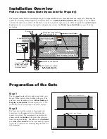
Preparation of the Gate

Step 1

The gate 

must

 be plumb, level, and swing freely on its

hinges.  Wheels must not be attached to the gate.  The
gate must move throughout its arc 

without binding or

dragging on the ground

.  

Note that gates over 250 lb.

should have ball bearing hinges with grease fittings.

Step 2

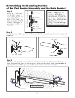
The fence post must be secured in the ground with
concrete so it will minimize twist or flex when the
opener is activated.  We recommend you position the
opener near the 

centerline

 of the gate to keep the gate

from twisting and flexing.  The addition of a 

horizontal

or vertical cross member

 (if one is not already in place)

to provide a stable area for mounting the gate bracket is
also important.

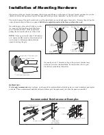
Installation Overview

Pull-to-Open Gates (Gate Opens into the Property)

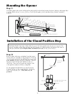
The diagram shown below is an example of a pull-to-open installation on a chain link fence and single gate.  Mounting the
opener on a masonry column requires special procedures; 

see


Column Installation Information


on page 36

 if you intend

to mount the opener on a column.  Furthermore, if you have a push-to-open gate, you will need to purchase a 

push-to-open

bracket

 (see

 Accessory Catalog

) to properly configure your system.  See 

Push to Open Installation


on page 30

 before

proceeding.

Horizontal Cross Member

Vertical Cross Member


Horizontal Cross Member

Gate Swings Evenly and Freely
Hung Firmly and Plumb

Receiver

Post Bracket Assembly

Control Box with Battery 

Gate Bracket

Single Gate Opener

Fence Post Set in Concrete

Run 1000' (max.) of low
voltage wire to control
box from transformer
(wire not included).           

Power Cable

Closed Position Positive Stop Plate

120 Volt indoor
Transformer

(surge protector 

not supplied)

PVC conduit (not included)
to protect wire from lawn
mowers and weed eaters.


Warning Sign

Содержание PRO-SW2500

Страница 1: ...lity for all liability and use of this product releasing GTO Inc from any and all liability If you are not in agreement with this disclaimer or do not feel capable of properly following all installati...

Страница 2: ...ess locations not servicing the general public in which unauthorized access is prevented via supervision by security personnel The GTO PRO SW 2500 Gate Opener is intended for use with vehicular swing...

Страница 3: ...ounting the Opener page 16 Installation of the Closed Position Stop page 16 Mounting the Control Box page 17 Connecting the Power Cable page 18 Powering the System page 19 Solar Chart page 19 Connecti...

Страница 4: ...obstruct and stop The GTO PRO SW2500 Operator accommodates extra transmitters digital keypads solar panels push buttons automatic gate locks and other access control products These optional accessori...

Страница 5: ...in contract tort or any other legal theory during the course of the warranty or at any time thereafter The installer and or user agree to assume responsibility for all liability and use of this produc...

Страница 6: ...er is proper for the type and size of gate its frequency of use and the proper class rating 2 Make sure the gate has been properly installed and swings freely in both directions Repair or replace all...

Страница 7: ...ld be pinched 3 Devices such as contact sensors safety edges and non contact sensors photo beams provide additional protection against entrapment 4 If push buttons or key switches are installed they s...

Страница 8: ...y cloth and apply silicone spray to it at least once per month 7 Service the gate and gate opener regularly Grease hinges and replace the battery every 3 5 years 8 To operate this equipment safely YOU...

Страница 9: ...operators utilize Type A an inherent i e built in entrapment sensing system as the primary type of entrapment protection Also the GTO PRO gate operator has provisions for the connection of Type B2 pr...

Страница 10: ...rning signs alert people of automatic gate operation and are required when installing the GTO PRO gate operator Furthermore a walk through gate must be installed if pedestrian traffic is expected near...

Страница 11: ...da USA Disconnect operator ONLY when the control box power switch is OFF and the gate is NOT moving LISTED US C Avisos de advertencia 2 suministrados que deben instalarse uno en cada lado de la puerta...

Страница 12: ...8 x 2 Bolt 1 3 8 x 3 Bolt 2 3 8 x 8 Bolt 4 8 Nylon Cable Tie 14 3 8 Washer 9 3 8 Lock Washer 7 5 16 Washer 1 3 8 Nut 7 5 16 Nut 1 Hardware Gate Opener 1 w 6 Power Cable Gate Bracket 1 Post Pivot Brack...

Страница 13: ...meter or 6 square see page 12 If your fence post is larger than 6 in diameter you will need threaded rods or carriage bolts longer than 8 See page 15 PVC conduit If you have thin walled tube or panel...

Страница 14: ...Hz Opener length with push pull tube fully retracted is 401 4 mounting point to mounting point Adjustable auto close timer and obstruction sensitivity Power terminal block accommodates a transformer o...

Страница 15: ...shown below is an example of a pull to open installation on a chain link fence and single gate Mounting the opener on a masonry column requires special procedures see Column Installation Information o...

Страница 16: ...r or 6 square should be made of metal instead of wood so that it will remain stable while the opener is moving the gate On round posts of 6 diameter or larger the post pivot bracket may not be necessa...

Страница 17: ...post pivot bracket as shown Fasten a 3 8 lock washer 3 8 washer and 3 8 nut on the end of the bolt DO NOT overtighten the nut because the post pivot bracket will have to be adjusted later Step 4 Attac...

Страница 18: ...nd readjust the pivot bracket until you can achieve these important clearances With the post pivot bracket in the optimum position for clearance and freedom of movement reattach the opener to the gate...

Страница 19: ...t supplied must be used Step 10 Mark reference points for bolt holes on the gate cross member through middle of gate bracket slots Drill 3 8 holes into the gate cross member as marked Mount gate brack...

Страница 20: ...e the gate remember to support opener Fasten the closed position stop plate to the end of the gate frame on the gate centerline but do not tighten it completely Slide the stop plate toward the fence p...

Страница 21: ...the ground to protect it from rain splash snow etc and at least 3 feet from an AC power source to prevent electrical interference Use mounting holes and screws provided to mount control box to a secur...

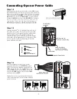
Страница 22: ...ve the control box cover and slide the battery into position with its terminals to the RIGHT see illustration Connect the BLACK battery wire to the NEGATIVE battery terminal Connect the RED battery wi...

Страница 23: ...s outlet to the control box following the path where the wire will be laid After you have measured how much wire is needed cut the wire to the appropriate length The table and map illustrate the maxim...

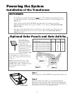
Страница 24: ...ate opener to function and will cause the system to go into a condition known as low voltage lockout NEVER splice wires together Splicing permits corrosion and seriously degrades the wire s ability to...

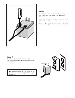
Страница 25: ...trol box to discourage insects from entering it and damaging the control board Step 6 Strip 1 2 of insulation from the ends of the low voltage wire Attach these stripped ends to the transformer termin...

Страница 26: ...if you have a Push to Open gate application you will need a Push to Open bracket see Push to Open Instructions on page 30 DIP Switch 5 B2 D1 Mode This DIP Switch must remain in the OFF position unless...

Страница 27: ...on has been achieved proceed to step 3 Step 3 With the gate in the desired closed position PRESS HOLD the SET LIMIT button on the control board for 5 seconds Step 4 Press the transmitter button and al...

Страница 28: ...f force the opener will apply to an ob struction before it automatically stops and reverses direction for approximately two 2 seconds Use a small slotted screwdriver to turn the arrow in the center of...

Страница 29: ...A X GRN BLK RED RECEIVER COM COM CYCLE CLOSE SAFETY EXIT OPEN SHADOW LOOP CLOSE EDGE OPEN EDGE J11 J8 J12 2 Set the transmitter DIP Switches There are nine 9 transmitter DIP switches each can be place...

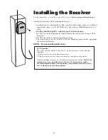
Страница 30: ...T run cable in conduit containing ac wiring The receiver range can vary from 50 to 100 feet depending upon weather topography and external interference NOTE Do not mount upside down FCC Regulation Thi...

Страница 31: ...ety device wiring to the terminal blocks Unplugging the transformer does not turn power to the opener OFF Contact Sensor Input Connection Connect one of the OPEN EDGE contact sensor wires to the COMMO...

Страница 32: ...ASE NOTE Non contact sensors are not included with the GTO PRO SW 2500 Shadow Loop If not installing a shadow loop skip to next section Refer to the sensor manufacturer s instructions for information...

Страница 33: ...blocks Unplugging the transformer does not turn power to the opener OFF Accessory Input Connection Connect one of the accessory wires to the COMMON COM terminal and the other to the CYCLE CLOSE termi...

Страница 34: ...racket 3 8 Lock Washer Post Bracket Assembly 3 8 Washer Step 2 After verifying that you have the best position for the post pivot bracket insert the 5 16 x 1 3 4 bolt through the aligned holes of the...

Страница 35: ...ON The control board is now configured to push the gate open Setting the Open Position Limit Step 1 Confirm that the power switch is in the ON position and the gate is in the CLOSED POSITION Step 2 Ac...

Страница 36: ...ll need to CLEAR your OPEN LIMIT settings and follow steps one 1 to four 4 again CLEARING PROGRAMMED OPEN LIMIT SETTING If you make a mistake and set the limit at the wrong position press your transmi...

Страница 37: ...wn and green should be 5 vdc without the arm connected If the board is good the arm will need repair 3 Mighty Mule 500 502 PRO SW2500 2502 PRO SW3000 3200 and PRO SW4000 4200 The battery could be very...

Страница 38: ...mer is unplugged Red LED 1 The Red LED comes on whenever the battery is fully charged Any time power is drained from the battery to operate the gate the light goes off until the battery is fully charg...

Страница 39: ...eep when the remote is pressed or when an accessory is used d If the unit is not working the battery is not connected or there is a loose connection Check the wires that connect to the battery and whe...

Страница 40: ...toward the column It is recommended that you place a steel plate between the opener mounting brackets and masonry surface for additional strength B If a push to open installation is impossible due to...

Страница 41: ...ncluded Digital Keypad F300 The specially designed digital keypad can be easily installed as a wireless or wired keypad It can be programmed to use up to fifteen different personal identification numb...

Страница 42: ...ransformer RB570 Standard 18 volt AC transformer for maintaining the battery included with the GTO PRO SW 2500 gate operator This is the only transformer approved for use with all UL325 GTO PRO gate o...

Отзывы: