background image

Chapter  2  Battery  Installation 

24       


  MUST400_User manual_EN_REV02    User Manual 

leak from the battery. Therefore, be sure to wear a pair of protective glasses, rubber gloves and skirt 

when operating the battery. Otherwise, you may become blind if acid enters your eyes and your skin 

may be damaged by the acid. 


At the end of battery life, the battery may have internal short circuit, drain of electrolytic and erosion 

of  positive/negative  plates.  If  this  condition  continues,  the  battery  may  have  temperature  out  of 

control, swell or leak. Be sure to replace the battery before these phenomena happen. 


If a battery leaks electrolyte, or  is otherwise physically damaged, it must be replaced, stored in a 

container resistant to sulfuric acid and disposed of in accordance with local regulations. 


If electrolyte comes into contact with the skin, the affected area should be washed immediately with 

water.


2.2 Battery cabinet typologies 

According to the requested UPS configuration may need internal and/or external batteries Modular UPS can 

utilize two different battery typologies: 


Modular: consisting of a number of battery boxes each containing 10 batteries that cannot be accessed 

w/o removing a protective cover, installed in the UPS and / or in a dedicated Modular Battery Cabinet 

(MBC)  that  allows  to  extend  the  runtime  as  long  as  the  systems  or  it’s  requirements  grown  adding 

additional battery modules on-the-fly by means of touch free blind mate connectors. 


Traditional: consisting of one or more strings of battery blocks installed on shelves in a locked cabinet 

or dedicated battery room 

Note 

The battery modules, regardless if they are mounted internally to the UPS or in the MBC, make uses of 

strings of 40 batteries. 

The Traditional external battery cabinet can make use of each even number of battery per string between 

36 and 44. 

The default factory setting, if the unit is ordered w/o internal battery is 40 batteries. 

The cabinet is only for valve regulated maintenance-free lead-acid battery. 

CAUTION: The lead acid battery may cause chemistry hazard


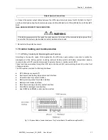
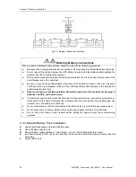
2.2.1 Modular Battery Cabinet 

Warning 


Use insulated glove to move battery modules. 


Do not to OPEN the battery boxes. 


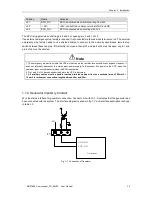
Voltage between points 1 and 2 ( fig. 2-1) may exceed 150V DC, so they must not be touched and 

the cover shall be kept on when not installed 

CAUTION: The lead acid battery may cause chemistry hazard


警告


危 险


警告


危 险


Содержание MUST400

Страница 1: ...MUST400_User manual_EN_REV02 User Manual 1 Modular UPS MUST400 USER Manual...

Страница 2: ...cur when starting the equipment should be taken into account when selecting instantaneous RCCB or RCD devices Residual Current Circuit Breakers RCCBs must be selected sensitive to DC class B and insen...

Страница 3: ...IS POTENTIALLY LEATHAL Battery manufacturers supply details of the necessary precautions to be observed when working on or in the vicinity of a large bank of battery cells These precautions should be...

Страница 4: ...ommunication 17 1 7 1 UPS Dry Contact GJ and Monitoring Board FK Features 17 1 7 2 Dry Contact Interface of Battery and Environmental Temperature Detection 18 1 7 3 Remote EPO Input Port 18 1 7 4 Gene...

Страница 5: ...9 Soft start 45 Chapter 6 Operating Instructions 46 6 1 Introduction 46 6 1 1 Power Switches 46 6 2 UPS Startup 46 6 2 1 Start Up Procedure 47 6 2 2 Procedures for Switching Between Operation Modes 48...

Страница 6: ...Environmental Characteristics 65 9 3 Mechanical Characteristics 66 9 4 Electrical Characteristics Input Rectifier 66 9 5 Electrical Characteristics Intermediate DC Link 67 9 6 Electrical Characterist...

Страница 7: ...re to 4 wire conversion transformer is provided as an optional part WARNING battery hazards SPECIAL CARE SHOULD BE TAKEN WHEN WORKING WITH THE BATTERIES ASSOCIATED WITH THIS EQUIPMENT After battery co...

Страница 8: ...generate some amount of hydrogen and oxygen at the end of charging so the fresh air volume of the battery installation environment must meet EN50272 2001 requirements The environmental temperature of...

Страница 9: ...d stable To guarantee optimize working lifetime the place chosen must guarantee Space for easy operation on the UPS Enough air to dispel heat produced by UPS Protection against atmospheric agents Prot...

Страница 10: ...its fitted with batteries Keep such moves to a minimum 1 4 3 Distances Required for Operating It s no necessary to leave free space in lateral part of the UPS To permit first commissioning the tighten...

Страница 11: ...Installation MUST400_User manual_EN_REV02 User Manual 11 System Unit Bypass Moudle Power Module Power Connection a 10 module cabinet System Unit Bypass Moudle Power Module Power Connection b 6 module...

Страница 12: ...ules and Battery Modules The number and positions of the Power Modules and Battery Modules may change according to the chosen factory configuration It s not possible to install a power module instead...

Страница 13: ...on engineers The installation engineers should have the knowledge of the wiring standards and the equipment to be installed 1 5 1 Rectifier and Bypass Input Supply of the UPS Over currents Install sui...

Страница 14: ...be installed upstream of the input distribution to avoid wrong alarm The residual current introduced by RFI filter in the UPS is between 3 5mA and 1000mA It is recommended to confirm the sensitivity...

Страница 15: ...2 Take special care when determining the size of the output and bypass neutral cable as the current circulating on the neutral cable may be greater than nominal current in the case of non linear loads...

Страница 16: ...pending on the type of installation Common Input Connections 4 For common bypass and rectifier inputs connect the AC input supply cables to the UPS input terminals input A B C N Refer to Fig 4 11 and...

Страница 17: ...to the specific needs of the application the UPS may need auxiliary connection to realize the management of the battery system including external battery switch and battery temperature sensor communi...

Страница 18: ...e detection J3 2 Environment temperature detection Note Specified temperature sensor is required for temperature detection R25 5Ohm B25 50 3275 please confirm with the manufacturer or contact local ma...

Страница 19: ...in 2 of J4 must be shorted 1 7 4 Generator Input Dry Contact J5 is the status interface for generator connection Connect J5 2 with J5 1 it indicates that the generator has been connected with the syst...

Страница 20: ...6 BCB_DRV BCB_CONT J6 J7 BCB_ONL 24V 24V 24V Fig 1 8 BCB Interface Table 1 6 Description of BCB Interface Note In case of BACKFEED protection option required the system change the meaning of the cont...

Страница 21: ...attery warning dry contact interface description Position Name description J8 1 BAT_LOW_NC Battery warning relay normally closed will be open during warning J8 2 BAT_LOW_NO Battery warning relay norma...

Страница 22: ...rface for utility failure warning when the utility fails the system will send a utility failure warning information and provide an auxiliary dry contact signal via the isolation of a relay The interfa...

Страница 23: ...e potential difference of more than 150V shall not be contacted at the same time If it is unavoidable insulated terminal cover and insulated cables shall be used for connection If external batteries a...

Страница 24: ...isting of a number of battery boxes each containing 10 batteries that cannot be accessed w o removing a protective cover installed in the UPS and or in a dedicated Modular Battery Cabinet MBC that all...

Страница 25: ...rds to prevent raising the center of gravity Install the batteries reliably and avoid vibration and mechanical bumping The bending radius of cable should be more than 10D where D is the outer diameter...

Страница 26: ...egative terminals Reverse connection of battery polarities will result in explosion fire accident the damage of batteries and UPS and human injury The battery connection terminals shall not subject to...

Страница 27: ...correct batteries setting in the battery setting menu Fig 2 3 LCD battery setting menu In particular 1 Number of batteries standard configuration is 40 2 Battery capacity for correct management of re...

Страница 28: ...charged automatically and the actual load must exceed 25 of the rated UPS kVA capacity If the load is less than 25 auto discharge cannot be executed The periodic interval can be set from 720 to 3000 h...

Страница 29: ...que Otherwise there is risk of fire CAUTION Use batteries with the same capacity and type if battery is replaced by an incorrect type it can cause explosion and damage of the equipment Do not replace...

Страница 30: ...ule remotely Note 1 The remote EPO switch must provide normally open or normally closed dry contact signals 2 The open circuit voltage is 24Vdc and the current is less than 20mA 3 Normally closed EPO...

Страница 31: ...f presenting higher reliability In order to assure that all modules are equally utilized and to comply with relevant wiring rules the following requirements apply 1 All UPS modules shall be of the sam...

Страница 32: ...nect cable 1 and cable 2 as fig 3 2 b 3 2 7 Control Cables Parallel control cable The parallel control cables are designed to be shielded and double insulated and are connected between the UPS systems...

Страница 33: ...u icon in home page of LCD To enter in this menu is necessary password level 2 Fig 3 4 Parallel setting parameters Set or verify the following parameters highlighted above in red System United 2 paral...

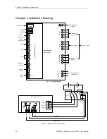
Страница 34: ...s Supply Power Cables External Batt N To External Battery Connection Dry Contact Board GJ SNMP SNMP Card RS232 RS485 J2 J3 J4 J5 J6 J7 J8 J9 J10 Batt Temperature ENV Temperature EPO GEN BCB Batt Low A...

Страница 35: ...drive signal BCB STATUS J6 2 BCB contactor status normally opened Shorted to GND when activated GND J7 1 ground System Unit Bypass Moudle PDU Module Power Module Internal Battery Breaker Battery Block...

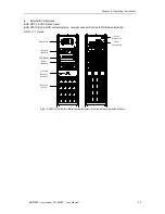
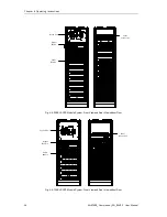
Страница 36: ...User Manual System Unit Bypass Moudle Power Module Power Connection Fig 4 4 200KVA UPS Module System Front View and Rear View without Door System Unit Bypass Moudle Power Module Power Connection Fig 4...

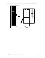
Страница 37: ...Chapter 6 Operating Instructions MUST400_User manual_EN_REV02 User Manual 37 200K UPS Fig 4 6 200KVA UPS External Dimensions Top view...

Страница 38: ...Chapter 6 Operating Instructions 38 MUST400_User manual_EN_REV02 User Manual Fig 4 7 120KVA UPS External Dimensions Fig 4 8 60KVA Built in Battery UPS Module System External Dimensions...

Страница 39: ...apter 6 Operating Instructions MUST400_User manual_EN_REV02 User Manual 39 a 200KVA UPS power connection b 120KVA UPS power connection Fig 4 9 Power Connection of Module System UPS Fig 4 10 Power Modu...

Страница 40: ...4 Wait for 5 minutes before inserting the removed modules 4 1 Internal Battery Module 4 1 1 Appearance of Internal Battery Module Fig 4 12 Battery Module According to the selected configuration the b...

Страница 41: ...e When using modular battery it is important to install at least 2 battery module per each power module installed Not doing this the internal fuses will open before reach the EOD Battery housed in the...

Страница 42: ...lse width modulation PWM associated with fully digital signal processing control DSP which features high reliability and convenience for use As shown in fig 5 1 the AC input mains source is supplied i...

Страница 43: ...load transfer between the inverter output and static bypass line the inverter output and bypass supply must be fully synchronized during normal operating conditions This is achieved through the invert...

Страница 44: ...overload capacity is exceeded under normal mode or if the inverter becomes unavailable for any reason the static transfer switch will perform a transfer of the load from the inverter to the bypass sou...

Страница 45: ...s 5 2 9 Soft start This function permit to absorb in gradual mode from mains after battery mode Through MTR setting software see appendix c for installation is possible to set delay from 3sec to maxim...

Страница 46: ...ine This mode can be regarded as a temporary transition mode between the normal mode and maintenance bypass mode or a temporary abnormal operating status Maintenance mode UPS Shuts down the load is co...

Страница 47: ...attery indicator Red Bypass indicator Green Inverter Indicator Off Load indicator Green Status indicator Red Note The output circuit breaker Q3 must be closed first followed by input circuit breaker Q...

Страница 48: ...his time the battery indicator flashes green It stops flashing and becomes solid green about 10 seconds after the rectifiers enter normal operation The inverter starts up automatically the green inver...

Страница 49: ...ntain the module wait for 10 minutes to let the DC bus capacitor fully discharge before removing corresponding module When the maintenance bypass switch is in ON position some part of the UPS circuit...

Страница 50: ...ker and battery breaker 6 6 Auto Start Commonly the UPS rack is start up on static bypass When the mains power fails the UPS draws power from the battery system to supply the load until the battery vo...

Страница 51: ...efore operation 3 After finishing the maintenance of the power module insert the power module in the frame the inserting interval for each module is longer than 10s the power module will automatically...

Страница 52: ...enu 3 Select the language and make sure At this time all the words in the LCD will be displayed in the selected language 6 10 Changing the Current Date and Time To change system date and time 1 In mai...

Страница 53: ...panel the operator can operate and control the UPS and check all measured parameters UPS and battery status event and history logs The operator control panel is divided into three functional areas as...

Страница 54: ...ss indicator Steady green UPS is working in bypass mode Steady red Bypass is failure Flashing red Bypass voltage is abnormal Off Bypass is normal and is not working Inverter indicator Steady green Inv...

Страница 55: ...ic bypass and battery TAB Select ENTER Confirm ESC Exit 7 1 4 Battery Pack Indicator The LED on the front panel of battery pack indicates battery pack status If battery fuse in battery module is broke...

Страница 56: ...g used only for manufacturer Battery data battery parameter setting used for service engineer Test battery self test battery maintenance Functional keys used by service staff fault clear history log c...

Страница 57: ...leled Mute on off Current status M1 M2 M3 M4 M5 M6 M7 M8 M9 M10 O P data O P wave LCD set Fig 7 3 Menu Tree Structure 7 3 Detailed Description of Menu Items The LCD main display shown in fig 7 3 is de...

Страница 58: ...emp Battery voltage V Positive and negative battery voltage Battery current A Positive and negative battery current Battery Temp Battery Temperature Remaining Time Min Remained battery backup time Bat...

Страница 59: ...ctory Rated information System rated information Module model 7 4 UPS Event Log The follow table 7 8 gives the complete list of all the UPS events displayed by history record window and current record...

Страница 60: ...t is over the limitation If bypass current is under 135 of the rated current The UPS alarms but has no action 21 Byp Ov Load Tout The bypass overload status continues and the overload times out 22 Byp...

Страница 61: ...bove 100 of nominal rating The alarm automatically resets once the overload condition is removed 1 Check which phase has overload through the load displayed in LCD so as to confirm if this alarm is tr...

Страница 62: ...minutes discharging with full load 41 Batt Reverse Battery cables are connected not correctly 42 N INV Protect The N Power Module Inverter Protect Check Whether inverter voltage is abnormal Whether in...

Страница 63: ...lace each filter 1 Open the UPS front door and locate the filters on the back side of the front door see Fig 8 1 2 Remove one bracket and remove the screws on the second bracket The second bracket nee...

Страница 64: ...s please refer to section 3 2 8 3 Dual input For dual input connection and installation refer to section Appendix A 8 4 Backfeed protection The system provide free contact available for disconnecting...

Страница 65: ...quirements of UPS EN50091 3 IEC62040 3 AS 62040 3 VFI SS 111 Note The above mentioned product standards incorporate relevant compliance clauses with generic IEC and EN standards for safety IEC EN AS60...

Страница 66: ...Weight kg 120 151 182 Color N A Black Protection Level IEC 60529 N A IP20 Module type Unit 10 20 Mechanical Dimension W D H mm 440 590 134 Weight kg 21 22 5 Color N A Black front no colour other side...

Страница 67: ...charge mode Temperature compensation mV C cl 3 0 selectable from 0 5 0 25 C or 30 C or inhibit Ripple voltage V float 1 Ripple current C10 5 Boost charge voltage V cell VRLA 2 4V cell selectable from...

Страница 68: ...Capability3 100 Neutral current capability 170 Steady state voltage stability 1 balanced load 1 5 100 unbalance load Transient voltage response4 5 THD 1 5 linear load 5 non linear load3 Synchronizati...

Страница 69: ...oad 100ms Superior protection bypass line N A Thermal magnetic breaker the capacity is 125 of rated current output IEC60947 2 curve C Current rating of neutral cable A 1 7 In Frequency Hz 50 60 Switch...

Страница 70: ...9 8 Efficiency Air Exchange Rated Efficiency kVA Unit 40 120kVA Efficiency Normal mode dual conversion 95 ECO mode 98 Battery discharging efficiency DC AC battery at nominal voltage 480Vdc and full ra...

Страница 71: ...ndependent bypass power supply and connect to the power supply through a separate switch Where a separate power source is not available the bypass and rectifier input supply connections are linked Not...

Страница 72: ...A Split Bypass Input 72 MUST400_User manual_EN_REV02 User Manual Bypass input Linked Bars PE Output Mains input Battery c Connection of 200KVA Modular System Fig B 1 Split Bypass Connection of Modula...

Страница 73: ...n a label behind the UPS door To communicate with PC server verify the setting on UPS Mimic Panel select Comm Set set Protocol SNT UPSilon use description UPSilon is a UPS monitoring and shutdown soft...

Страница 74: ...oftware permit to do all setting available in the setting Wrong setting can damage the system batteries or the equipment load Wrong setting made by not trained personnel invalid the warranty Here belo...

Страница 75: ...re Select the right UPS type Select the Baud rate Select protocol mode MODBUS_RTU Select the COM port number used in the PC Click on connect icon and start the communication WARNING MTR software doesn...

Отзывы: