3- Turn the instrument on and select the appropriate cycle for the engine under
measurement.
4- Select the desired mode and view.
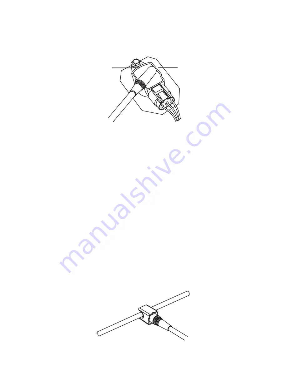
5- Place the COP sensor on the top and center of the ignition module (as shown in the
Fig. 12), and observe whether the instrument is able to detect and display the desired
measurement.
Fig. 12 - Using the COP sensor on a ignition module
6- If the instrument is unable to detect the ignition system signal, it may be necessary to
reposition the sensor so that a consistent signal is detected and displayed.
NOTES
• The position of the sensor and the particular design of the ignition module may
affect the signal’s shape shown when the waveform display is selected. In order to
compare waveforms between several cylinders’ ignition modules, the placement of the
sensor relative to the ignition module should be kept as consistent as possible for all the
measurements.
• In some engines, the ignition modules are located very close together, and in rare
occasions this could cause the instrument’s sensor to detect signals from nearby modules,
leading to inconsistent measurements. This can usually be solved by changing the
placement or orientation of the sensor on the ignition module.
7.4 Measuring ignition systems with (high voltage) spark plug wires
1- Ensure the instrument is turned off.
2- Insert the SPW or Clip-on SPW sensor barrel connector plug into the flexible probe or
extension cable receptacle.
3- Turn the instrument on, and select the appropriate cycle for the engine under
measurement.
4- Select the desired mode and view.
5- If using the SPW sensor, place the spark plug wire into the slot of the sensor, and as far
as possible from other spark plug wires trying to maintain a right angle (90°) between
the sensor and the wire.
Spark plug wire SPW sensor
Fig. 13 - Using the SPW sensor on a spark plug wire
Page 12
COP sensor
Ignition module


