background image

Geophysical Survey Systems, Inc. 

PaveScan® RDM 2.0 


Manual 

MN36-716 Rev A 

50 

When the 

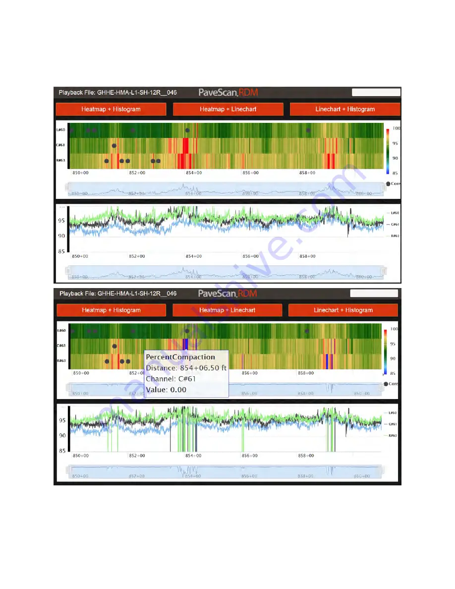
Apply Valid Data Range

 button is checked, all values outside the specified range are replaced 

by zeros in the display. The two images below show percent compaction data from a file before (top), and 
after (bottom) applying a Valid Range filter from 85 – 100%.  


Содержание PaveScan RDM 2.0

Страница 1: ...MN36 716 Rev A ...

Страница 2: ...rights reserved including the right of reproduction in whole or in part in any form Published by Geophysical Survey Systems Inc 40 Simon Street Nashua New Hampshire 03060 USA Printed in the United States SIR RADAN UtilityScan and PaveScan RDM are registered trademarks of Geophysical Survey Systems Inc ...

Страница 3: ...sportation and insurance pre paid without alteration or further damage and which in GSSI s judgment were defective or became defective during normal use GSSI ASSUMES NO LIABILITY FOR ANY DIRECT INDIRECT SPECIAL INCIDENTAL OR CONSEQUENTIAL DAMAGES OR INJURIES CAUSED BY PROPER OR IMPROPER OPERATION OF ITS EQUIPMENT WHETHER OR NOT DEFECTIVE Before returning any equipment to GSSI a Return Material Aut...

Страница 4: ...Geophysical Survey Systems Inc PaveScan RDM 2 0 Manual MN36 716 Rev A ...

Страница 5: ... 5 Data Collection 23 Chapter 3 Data Playback and Export 29 3 1 Playback and Review Collected Files 29 3 2 Setting Up the Void Percentage Relationship 34 3 3 Exporting Collected Files 36 Chapter 4 System Shutdown and Updates 41 4 1 System Shutdown 41 4 2 Software Updates 42 Appendix A Calculation of Voids Compaction or Density from Dielectric 45 Appendix B Choosing the Correct Lateral Offset 47 Ap...

Страница 6: ...Geophysical Survey Systems Inc PaveScan 2 0 RDM Manual ...

Страница 7: ... A packing list is included with the shipment that identifies all the items included in the order Please check the shipment against the packing list upon receipt of the shipment If an item is found missing or was damaged during the shipment please call or fax your sales representative to immediately report the problem The PaveScan RDM system contains the following items 1 Panasonic G1 ToughPad wit...

Страница 8: ...Geophysical Survey Systems Inc PaveScan RDM 2 0 Manual MN36 716 Rev A 2 ...

Страница 9: ...ntrator box The power light illuminates and the sensors are powered up 2 Power up the ToughPad computer by pressing and holding down the power button until the green light just to the left of the power button lights up The computer takes 20 30 seconds to start After it is fully started the Main Menu of the PaveScan RDM application appears Main Menu 3 If there are no sensor s detected by the system...

Страница 10: ...y Systems Inc PaveScan RDM 2 0 Manual MN36 716 Rev A 4 The application can also be started via a desktop shortcut that appears on the desktop after the application is shutdown Application Shortcut double click to start ...

Страница 11: ...n enabling the editing of data files modification of data file information and the removal of data files see page 7 Options for removing Files Projects and Project Groups Project Groups are added using this option as well see page 10 Options to modify the number of measurements per unit distance see page 11 Pressing this button opens this manual as a PDF file The button returns the user back to th...

Страница 12: ...n enter in the calibration distance Recommended distance is 100ft 30m or more because the longer the calibration distance the more accurate the calibration 2 Next line up the cart at the starting point and press Start 3 Move the cart along the length of the measured distance then press Stop Press Save to accept the new calibration number or Cancel to keep the old one ...

Страница 13: ...er can adjust the density units Options include oz in3 lb ft3 g cm3 and kg m3 Use Stationing Format Check this to show distances in station format for example 5250 ft in station format is 52 50 Auto Start Distance When this option is selected the ending distance of the previous file is automatically specified as the starting distance for the next file The starting distance value is always editable...

Страница 14: ...positive Correspondingly if the GPS is to the right of the center sensor facing the direction of travel the value is negative GPS Time Lag seconds For high accuracy GPS systems the lag or time difference between the arrival of the PaveScan dielectric measurement and the GPS position information can be calculated and entered here This value is then used to correct the time synchronization between t...

Страница 15: ...fied each exported data point is an average of all the data points at the measurement location 0 25ft 10cm Distance File Measurement Interval The output interval between exported measurements For general purposes where data may be obtained over a distance of hundreds of feet an export interval of 0 5ft 20cm is useful Time File Moving Average When this value is non zero a central moving average of ...

Страница 16: ...ues in one column When this box is unchecked multi sensor data from one measurement location are written to one row Press the Save button to save all changes made in the Project Properties screen sub screens i e GPS Lane Names and Export Options File Management Options for removing Files Projects and Project Groups Additionally file properties such as starting distance and Y coordinate can be modi...

Страница 17: ...s m and 2 scans ft 8 scans m It is best to set the option to match the pace of the user and Walk is typically used There is an over speed indicator on the data collection screen so the user can adjust walking speed to ensure no measurements are skipped Advanced Options Advanced Options Screen Select the Advanced button to check for updates modify sensor settings or customize new project informatio...

Страница 18: ...n displays the Sensor Detection screen Sensor Detection Screen 2 The detected sensors appear in this table and the Collect Preview button is enabled The user can press Collect preview to preview collection using the last calibration NOTE The sensors serial numbers are displayed once the sensors are detected They may NOT be in order That option comes later ...

Страница 19: ...ct Settings screen appears This screen contains numerous items that the user can use to fill in project specific information For New Projects enter the new project name then press For Existing Projects the button is enabled When is pressed enter a new project name and then press The Save As option is useful to create a new project from an existing project s settings Note If the Status changes to S...

Страница 20: ...oncentrator box 1 2 or 3 sensors This is a read only field and is present for informative purposes only Location Optional entry for specifying information related to where the data are being obtained This information is exported with the data Reference Line Optional entry for specifying the reference used for the lateral coordinates assigned to a file Examples include curb outside lane stripe or p...

Страница 21: ...hat can be seen on the side of the sensor when it is mounted on the cart For example if Sensor serial 8 is located on the left side of the cart it should be positioned on the left side of the screen as shown in the image above If mounted on a vehicle the orientation of the sensors is what is seen as facing the direction of travel i e the left sensor would be on driver s side of the vehicle if the ...

Страница 22: ...ndicate the exact location of the core in the data file Starting Station Number This is that starting station number of the file If stationing is disabled accessed by Project Info button this entry will not appear When the Auto Start Distance Project option is selected accessed by Project Info button this value is automatically specified based on the ending distance of the previously collected fil...

Страница 23: ...he Playback Range menu Sublot Optional entry This is one of the filter options in the Playback Range menu File Name The first part of the output filename All files after the first file with the same name have numbers appended to them that increment from file to file For example if the first file name is MP101 the second file MP101_001 etc The Project Information screen is displayed where project i...

Страница 24: ...een If necessary or required the user is directed to perform air and metal plate calibrations Directs the user to the data collection screen to start a file This button turns green once the sensors are warmed up sufficiently The warm up status is shown by the progress bar at the top right ...

Страница 25: ... is green NMEA GPS sentences are being received by the Toughpad Note no indication of the quality of the GPS data is provided The rectangle adjacent to the right most icon indicates the level of the Toughpad battery in percent 2 4 Calibration If calibration is desired or necessary press the Calibration button and the calibration screen is displayed Air calibrations are required once a day and meta...

Страница 26: ...es the position of the sensor on the cart In the example below sensor 12 should be on the left side of the cart If it is not then the system should be shutdown and restarted with changes made to the Sensor Configuration 2 2 3 Place the metal plate underneath the sensor indicated Be sure to line up the metal plate so that the sensor laser is directed into the small hole in the center of the metal p...

Страница 27: ...f calibration is required The following is displayed if no calibration is required The following is displayed before the air calibration is performed and metal plate calibration is not required The following is displayed after the air calibration is performed and metal plate calibration is not required ...

Страница 28: ...ptions turn green when the option is available The Air button for the air calibration is first Once the air calibration is complete the other buttons turn green Perform the metal plate calibration 1 at a time by placing the metal plate underneath the appropriate sensor and pressing the correlating button ...

Страница 29: ...tion the scales of the charts have a followed by the serial number of the sensor At any time the dielectrics at a certain distance can be displayed by placing the pointer or touching at the desired location on the chart The current speed data can be collected in walk mode is about 5ft per second 1 5m s If this rate is exceeded by a small fraction the missing data points is filled in with duplicate...

Страница 30: ...Scan RDM 2 0 Manual MN36 716 Rev A 24 When backing up the current distance and dielectrics associated with the sensor positions are indicated at the top of the screen and the back up location in the data is indicated by a large black bar ...

Страница 31: ...rated physical property value on top and a linechart of the values on the bottom Shows a heatmap of the displayed values dielectrics or calibrated physical property value on top and a histogram showing the distribution of the displayed values on the bottom Shows a linechart of the displayed values dielectrics or calibrated physical property value on top and a histogram showing the distribution of ...

Страница 32: ...Geophysical Survey Systems Inc PaveScan RDM 2 0 Manual MN36 716 Rev A 26 By default the Heatmap Linechart combination is shown The heatmap histogram combination is shown below ...

Страница 33: ...ea being viewed can then be shifted by placing the pointer or touching and dragging the shaded area left or right Once the sensors are moved the area changes back to the default data collection area When finished collecting a data file press Stop and Save This redirects the user back to the File Information web page where custom changes can be made to the file information before collecting the nex...

Страница 34: ...Geophysical Survey Systems Inc PaveScan RDM 2 0 Manual MN36 716 Rev A 28 ...

Страница 35: ...ion screen using Playback Last 2 Any file can be played back by clicking on the Playback button from the Main Menu When accessing playback from the Playback button a screen appears specifying to playback one file or a range These options are described below This plays back one user selected file Displays a screen that allows a selection of different individual lines of data and specific distance r...

Страница 36: ...Playback screen include Allows user to edit file information such as starting distance ending distance and filename This plays back the selected file Shows the selected project information and allows the user to edit project information Allows user to export all files in the selected project folder Brings user back to the start up screen which allows access to data collection and system settings T...

Страница 37: ...2 0 Manual MN36 716 Rev A 31 A played back file is shown below Display start up screen Main Menu which allows access to data collection playback data and system settings Opens a screen which displays statistics related to the currently open file ...

Страница 38: ... cores used to generate a dielectric or compaction curve The columns shown contain the following information Relative Dielectric Average dielectric at the location using a 6 15cm central moving average screen Exports the data from the currently displayed file using the current display options This button accesses all the Display Options that can be adjusted during collection and playback ...

Страница 39: ...imum measurement value shown in both the heatmap and line chart Display Moving Average When this value is non zero a central moving average of the size specified is applied to each data point prior to display For example if a 0 5ft 20 cm moving average is specified each displayed data point is an average of all the data points at the measurement location 0 25ft 10 cm For time based files the units...

Страница 40: ... density obtained from cores Core Measurement Type The core physical property that is to be correlated to dielectrics Different options include Percent Compaction Percent Voids and Density A Value This is the first value used in the equation relating dielectric to another physical property see Appendix B for details B Value This is the second value used in the equation relating dielectric to anoth...

Страница 41: ...esponding core measured physical property i e Voids Compaction Density from up to 10 cores and then press the button 2 The calculated values are returned in a pop up screen that prompts the user to either save the values by pressing OK or not to save the values by pressing Cancel 3 By selecting OK the values are input into the A and B entries in the Core Calibration screen when the button is press...

Страница 42: ...in this subfolder The name of the file is the same as the filename with Exported Data appended to the end Below the file File__028 belonging to the project Daily Data 5 4 20 has been exported The exported file is an ASCII file containing a number of header lines containing project and file information followed by the exported data The exported data consists of comma separated values Skipping expor...

Страница 43: ... Station Station corresponding to measurement Only appears when Station option is checked in project properties The following columns appear for each sensor used during data collection Longitude Longitude of measurement from GPS in decimal degrees Latitude Latitude of measurement from GPS in decimal degrees Elevation Elevation of measurement in meters Lateral Offset Lateral offset of sensor from t...

Страница 44: ...me Stamp in seconds associated with measurement MPCal Time Stamp Time Stamp of Metal Plate calibration measurement used to calculate the dielectric All the files in a project are exported and a project statistics file is created when the button is pressed from the Select Playback File screen In addition there is a separate file containing statistics over specified distance ranges when the Provide ...

Страница 45: ...Google Earth KML file is automatically created when files and selected ranges are exported The KML file is located in the same folder as the exported data The display range of the values and value type i e dielectric or compaction in the KML file is the same display range used for Playback So what you see in playback is what you get when you export the data to a KML file Once the data is exported ...

Страница 46: ...Geophysical Survey Systems Inc PaveScan RDM 2 0 Manual MN36 716 Rev A 40 ...

Страница 47: ...sted Steps for updating the PaveScan RDM with the latest software package are also listed 4 1 System Shutdown The application is shutdown from the Exit button that is accessed by in the Main Menu The application screen closes and the screen desktop appears The final step is to press the power button on the concentrator box to power down the sensors Press this button to turn off power to sensors ...

Страница 48: ... 1 Open Windows Explorer locate the Zipped folder click on it and a setup file has a EXE extension is displayed on the right pane of the Windows Explorer screen 2 Drag and drop this folder onto the Windows desktop 3 After this is done double click on the Setup file icon on the desktop to start the installation of the new application version It automatically removes the older version before install...

Страница 49: ...own the application and power off the sensors Follow the start up procedure described in Section 2 1 If one or more sensors are still not recognized check all the connections and retry Several attempts may be required Note all the sensors connected must be detected for the detection process to be successful otherwise a No Sensors found status appears So in a worst case scenario connect only one se...

Страница 50: ...Geophysical Survey Systems Inc PaveScan RDM 2 0 Manual MN36 716 Rev A 44 ...

Страница 51: ...ectric The exponential equation takes the form P AeBd The linear equation uses the form P A Bd where P the measured physical property from the core which can be density voids or compaction A value obtained from least squares fit exponential or linear curve of P versus dielectric calculated from a number of calibration cores B value obtained from least squares fit exponential or linear curve of P v...

Страница 52: ...Geophysical Survey Systems Inc PaveScan RDM 2 0 Manual MN36 716 Rev A 46 ...

Страница 53: ...l Reference line in project info This reference must be used for the entire project The side of the Lateral Offset Reference is always on the side of the cart left or right RELATIVE to facing up station This is regardless the directly of paving and the direction of collection Choosing a Lateral Offset for a File During collection of a file the distance to choose for the lateral offset should be th...

Страница 54: ... above the Reference line is the center line dotted white line between the travel and passing lanes denoted by 0 In the left figure the joint between the breakdown lane and the travel lane yellow line has a lateral offset of 12L for the southbound figure and 12R for the northbound figure ...

Страница 55: ...This option is found in the Project Properties as a new checkbox Apply Valid Data Range When this option is checked a pre selected value range is used The value range is specified in the screen that appears when pressing the button Note there are valid range settings for Dielectric Percent Voids Compaction and Density ...

Страница 56: ...Rev A 50 When the Apply Valid Data Range button is checked all values outside the specified range are replaced by zeros in the display The two images below show percent compaction data from a file before top and after bottom applying a Valid Range filter from 85 100 ...

Страница 57: ...eophysical Survey Systems Inc PaveScan RDM 2 0 Manual MN36 716 Rev A 51 The statistics are only applied to the valid data as shown below The valid data range is written to the header of the exported file ...

Страница 58: ...ystems Inc PaveScan RDM 2 0 Manual MN36 716 Rev A 52 The values in the exported file outside the data value range are replaced by zeros The values outside the valid data range are excluded from the segment statistics file ...

Страница 59: ... to CSV and KML files The criteria defining the defects are accessible by pressing the Export Defect Settings button and are shown below The first four rows consist of threshold values where data values below or above the threshold are classified as defects Contiguous defects that meet the specified minimum length and or area size are exported The length of each data measurement is the spacing bet...

Страница 60: ...aveScan RDM 2 0 Manual MN36 716 Rev A 54 When the Export Defects button is checked six additional files are created when the playback file or playback range is exported Separate files are generated for defect lengths and defect areas ...

Страница 61: ...rting distance of the interval Start Station This column is present when Use Stationing Format is checked in the Project Properties Segment Length The length within the segment that contains data This may be less than the segment length at the beginning and or end of the file or selected playback range Lateral Offset The position of the profile that the data were obtained relative to the lateral o...

Страница 62: ...ationing Format is checked in the Project Properties screen Segment Length The length within the segment that contains data This may be less than the segment length at the beginning and or end of the file or selected playback range Profiles Number of profiles i e lines at different offsets used in the Defective calculation Measurements Number of valid measurements used in the Defective calculation...

Страница 63: ... the defect in terms of the distance along the file and the lateral offset The Start Station and End Station Columns are only present if Use Stationing Format is checked in the Project Properties screen The last four columns show the Latitude and Longitude of the starting and ending locations of the linear defects Note that for scenarios where the defect extends around a curve the GPS coordinates ...

Страница 64: ...Geophysical Survey Systems Inc PaveScan RDM 2 0 Manual MN36 716 Rev A 58 ...

Страница 65: ... of the defect in terms of file distance and lateral offset The Start Station and End Station Columns are only present if Use Stationing Format is checked in the Project Properties The last 8 columns provide the GPS coordinates of the 4 corners of the defect Note that for scenarios where the defect extends around a curve the GPS coordinates may not adequately describe the true area of the defect T...

Страница 66: ...Geophysical Survey Systems Inc PaveScan RDM 2 0 Manual MN36 716 Rev A 60 ...

Страница 67: ......

Страница 68: ...Geophysical Survey Systems Inc www geophysical com sales geophysical com 40 Simon Street Nashua NH 03060 3075 USA ...

Отзывы: