- 23 -
STC 4-16 CT CI
150
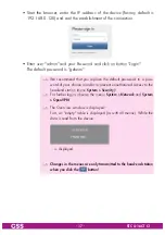
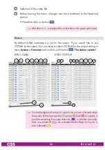
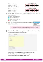
The upper value shows the current needed data rate.
The lower value shows the maximum possible output data rate (depend-
ant on the output settings).
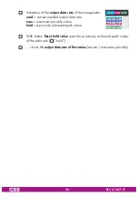
—> The background colour
in column
Line
indicates an output data
overflow.
In this case change the output settings or remove stations from the
data stream using the station filter.
151
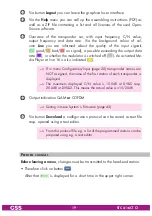
In column
Modulator
, switch on or off the modulators of the individual lines.
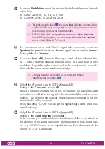
152
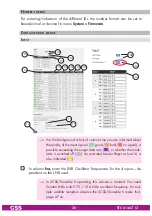
In column
Chan. / Freq. [MHz]
, enter the desired output channel/fre-
quency of the individual lines.
—> Double assignments are indicated by a
warning icon .
—> A
output signal
is normally transmitted
with a bandwidth of 8 MHz. This means
that you can only use the channel centre frequency of the existing
channel grid in the range of channels C21…C69 (frequency grid
8 MHz). The CCIR channel grid is 7 MHz in the range of the lower
frequency bands (channels C5 … C12). If 8 MHz QAM signal
packages are transmitted in these channel ranges, this will result in
interference (overlapping) and transmission problems.
For programming in these channel ranges and in the frequency rang-
es below them, we recommend starting with frequency 306 MHz
going back in steps of 8 MHz (see frequency table on page 55).
Please note thereby that many DVB-T receivers cannot receive the
channel ranges S21 … S41 (306 … 466 MHz).
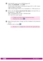
153
Only if the RF output is set to QAM (page 43):
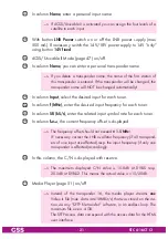
In column
SR [kS/s]
, enter the desired output symbol rate of the individual
lines.
—> The background colour
in column
Line
indicates an output data
overflow.
In this case increase the output symbol rate or the QAM modulation
or remove stations from the data stream using the station filter.


