


DA98D User Manual
49
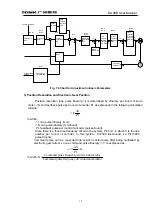
7.2 Trial Operation
1
)
Pre-operation Examination
After installment and wiring have been completed, the following items shall be examined
before switching on the power:
z
Whether the wiring and reliable input voltage are correct in the power supply terminal
TB.
z
Whether the power supply wire and motor wire have short circuit or ground contact.
z
Whether the encoder cable has correction wiring.
z
Whether the wiring, power supply electrode and voltage are correction in the control
signal terminal.
z
Whether the drive unit and motor have been firmly installed.
z
Whether the motor shaft is connected with load.
2
)
Trail Operation by Switching on Power
(1) Trail Operation
①
Connect CN1 and set the input control signals as: servo on (SON) OFF, CCW drive
stopping (FSTP) ON, CW drive stopping (RSTP) ON.
②
Switch on control circuit power (temporarily not switching on the main circuit power) and
the point on the display of the drive unit will shine. If alarm occurs, examine the wiring.
③
Set the control mode (parameter No.4) as speed trail operation mode (set as 2).
④
Switch on the main circuit power.
④
Render servo on (SON) ON after confirming that there is no alarm or any other abnormal
condition, then the motor will be activated and under the state of zero speed.
⑥
Enter the speed trial operation mode through key operation. The hint character for speed
trial operation is “S” and the value unit is r/min. When the system is under the speed
control mode, the speed command will be provided by the keys. The speed command
can be changed by
or and the motor will run at the given speed.
(2) JOG (Itching) Operation
①
Connect CN1 and set the input control signals as: servo on (SON) OFF, CCW drive
stopping (FSTP) ON, CW drive stopping (RSTP) ON.
②
Switch on control circuit power (temporarily not switching on the main circuit power) and
the point on the display of the drive unit will shine. If alarm occurs, examine the wiring.
③
Set the control mode (parameter No.4) as JOG operation mode (set as 3).
④
S
witch on the main circuit power..
⑤
Render servo on (SON) ON after confirming that there is no alarm or any other abnormal
condition, then the motor will be activated and under the state of zero speed.
⑥
Enter the speed trial operation mode through key operation. The hint character for speed
trial operation is “J” and the value unit is r/min. When the system is under the speed
control mode, the speed value and direction will be determined by the keys. With
,
the motor will run at the speed and direction determined by parameter No.21; with
,
the motor will run in the reserve direction at the given speed.
(3) Operation under Position Control Mode
①
Connect CN1 and set the input control signals as: servo on (SON) OFF, CCW drive
stopping (FSTP) ON, CW drive stopping (RSTP) ON.
②
Switch on control circuit power (temporarily not switching on the main circuit power) and
Содержание DA98D
Страница 1: ...DA98D Digital AC Servo Drive Unit User Manual V5 00 ...
Страница 15: ...DA98D User Manual 4 Fig 1 1 Appearance of Servo Drive unit 2 Servo motor appearance ...
Страница 16: ...DA98D User Manual 5 Fig 1 2 Servo Motor Appearance ...
Страница 23: ...DA98D User Manual 12 Fig 3 1 Standard Wiring for Position Control Mode AM26LS32 Receiver ...
Страница 24: ...DA98D User Manual 13 Fig 3 2 Standard Wiring for Speed Control Mode AM26LS32 Receiver ...
Страница 71: ...DA98D User Manual 60 Installation Dimension Drawing for BS 120 Model ...
Страница 72: ...DA98D User Manual 61 Installment Dimension Drawing for BS 200 Model ...
Страница 73: ...DA98D User Manual 62 Installment Dimension Drawing for BS 300 Model ...
Страница 74: ...DA98D User Manual 63 Installment Dimension Drawing for BD 80 Model ...
Страница 75: ...DA98D User Manual 64 Installment Dimension Drawing for BD 120 Model ...


