DA98D User Manual
39
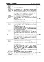
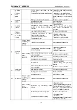
①
One phase of U, V and W is
disconnected.
②
Wrong connection of encoder.
Examine wire connection.
Occur when
switching on
control
power
Failure in circuit board.
Replace servo drive unit.
Disconnection of brake resistance. Re-wiring.
14
Braking
failure
Occur during
motor
operation
①
Damaged brake transistor.
②
Internal brake resistance is
damaged.
Replace servo drive unit.
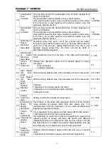
Insufficient capacity in the brake
loop.
①
Reduce stop/start frequency.
②
Reduce
acceleration/deceleration time.
③
Reduce torque limiting value.
④
Reduce load inertia.
⑤
Replace drive unit and motor
of greater frequency.
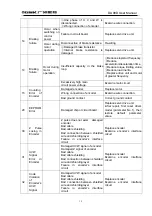
14
Braking
failure
Occur during
motor
operation
Excessively high main
circuit power voltage.
Examine main circuit.
Damaged encoder.
Replace motor.
Wrong connection of encoder.
Examine wire connection.
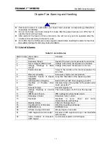
15
Counting
Error of
Encoder
Bad ground contact.
Correct ground contact.
20
EEPROM
Error
Damaged chip or circuit board.
Replace servo drive unit.
.After repair, first reset driver
model (parameter No.1), then
restore default parameter
value.
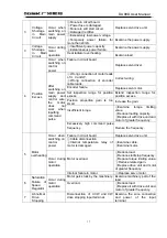
30
Z Pulse
Losing in
Encoder
Z pulse does not exist; damaged
encoder
Bad cable
Bad cable shielding
Bad connection between shielded
wire and shielding layer
Failure in encoder’s interface
circuit
Replace encoder
Examine encoder’s interface
circuit
31
UVW
Signal
Error in
Encoder
Damaged UVW signal of encoder
Damaged Z signal of encoder
Bad cable
Bad cable shielding
Bad connection between shielded
wire and shielding layer
Failure in encoder’s
interface
circuit
Replace encoder
Examine encoder interface
circuit
32
Code
Violation
of
Encoder’s
UVW
Signal
Damaged UVW signal of encoder
Bad cable
Bad cable shielding
Bad connection between shielded
wire and shielding layer
Failure in encoder’s
interface
circuit
Replace encoder
Examine encoder interface
circuit
Содержание DA98D
Страница 1: ...DA98D Digital AC Servo Drive Unit User Manual V5 00 ...
Страница 15: ...DA98D User Manual 4 Fig 1 1 Appearance of Servo Drive unit 2 Servo motor appearance ...
Страница 16: ...DA98D User Manual 5 Fig 1 2 Servo Motor Appearance ...
Страница 23: ...DA98D User Manual 12 Fig 3 1 Standard Wiring for Position Control Mode AM26LS32 Receiver ...
Страница 24: ...DA98D User Manual 13 Fig 3 2 Standard Wiring for Speed Control Mode AM26LS32 Receiver ...
Страница 71: ...DA98D User Manual 60 Installation Dimension Drawing for BS 120 Model ...
Страница 72: ...DA98D User Manual 61 Installment Dimension Drawing for BS 200 Model ...
Страница 73: ...DA98D User Manual 62 Installment Dimension Drawing for BS 300 Model ...
Страница 74: ...DA98D User Manual 63 Installment Dimension Drawing for BD 80 Model ...
Страница 75: ...DA98D User Manual 64 Installment Dimension Drawing for BD 120 Model ...


