GSi AIRSTREAM Скачать руководство пользователя страница 7

6

INSTALLATION

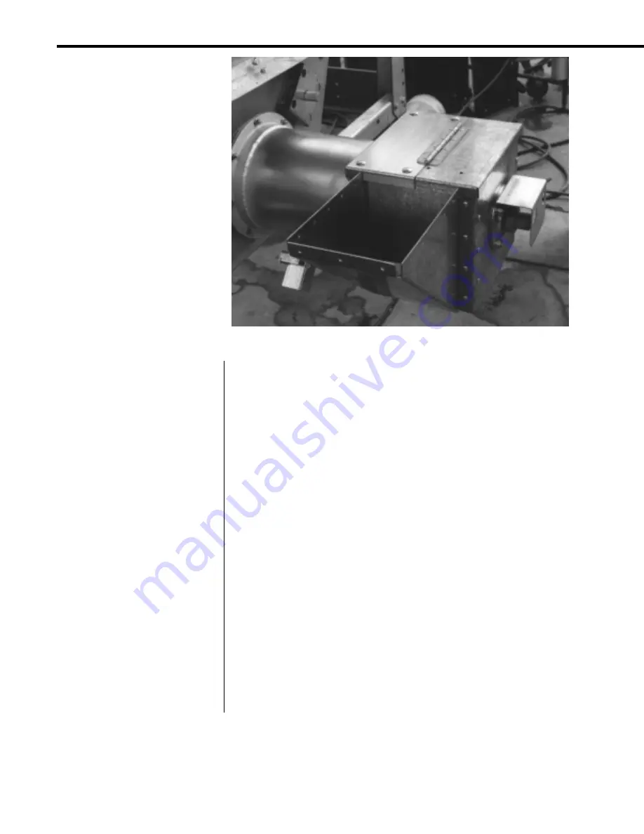
Modified discharge box with side discharge chute.

Determine which side of the
dryer the Aspirator will be
mounted.

GSI recommends mounting on the left side for the best performance,

however, the Aspirator can be mounted on either the left or right hand
side of the dryer.  This is done to fit most dryer sites where other
equipment (unloading equipment) may be installed around the dryer.
Some dryers have ladders on the rear bulkheads that must be taken into
account before mounting the Aspirator.

Do not compromise safety for convenience.

Install the 

Discharge Box Side

 onto the inside of the discharge box

with the large rectangular slot down.
Install the 

Discharge Box Bypass Chute

 onto the outside of the

discharge box.
Bolt these parts in with the 

1/4" bolts, locknuts, 

and

 washers.

Check that all bolts are tight and discharge box lid moves freely on its
hinge.

Discharge Box Modifications

The discharge box on the rear of the
dryer may need to be modified to
accept the parts of the settling
chamber.  If the Aspirator is ordered
with the dryer, these modifications
may have been done at the factory
as the dryer was manufactured.  If
the kit was purchased to install on
an existing dryer, these modifications
must be performed to install the
Aspirator unit.  The following
procedure outlines the necessary
steps for modifying the discharge box
assembly.

Remove the side of the
discharge box that is on the
same side that the Aspirator
will be mounted.

Remove the 

"Huck" bolts (14)

 that hold the box side to the box.

Cut the collar (inside box) with a hand-held grinder down the centerline of
the bolt, then across the bolt.  Hit each one with a hammer to pop it out
of the hole.
Remove the side of the discharge box that is to be replaced.

Install the new Discharge Box
Side
 and the Discharge Box
Bypass Chute.

Содержание AIRSTREAM

Страница 1: ...OWNER S MANUAL AIRSTREAM ASPIRATOR A I R S T R E A M G R A I N C O N D I T I O N I N G S Y S T E M S 1 9 9 6 PNEG 577 ALL ASPIRATOR MODELS JULY 1 1996...

Страница 2: ...tor 17 Cyclone Section Expanded Aspirator 19 Control Option 21 Operation 22 Basic Aspirator 22 Expanded Aspirator 23 Vacuum Hose Option Basic Aspirator 24 Vacuum Hose Option Expanded Aspirator 24 Serv...

Страница 3: ...DIFICATIONS TO THE PRODUCT NOT SPECIFICALLY COVERED BY THE CONTENTS OF THIS MANUAL WILL NULLIFY ANY PRODUCT WAR RANTY THAT MIGHT HAVE BEEN OTHERWISE AVAILABLE THE FOREGOING WARRANTY SHALL NOT COVER PR...

Страница 4: ...to read this manual and its safety instructions is a misuse of the equipment SAFETY ALERT SYMBOL SAFETY GrainSystems Inc recommends contacting your local power company and having a representative surv...

Страница 5: ...4 APPLICATIONS...

Страница 6: ...aspi rating fan to remove the material from the discharge box via a settling chamber The fan blows the mate rial to the polyethylene cyclone that separates the material from the air and settles it to...

Страница 7: ...all bolts are tight and discharge box lid moves freely on its hinge Discharge Box Modifications The discharge box on the rear of the dryer may need to be modified to accept the parts of the settling...

Страница 8: ...spacers with the angle away from the 6 hole Align the slide plate end of Vacuum Hose Adapter Weldment with Settling Box Fan Side so the 2 tube points down Bolt the Vacuum Hose Adapter Weldment to the...

Страница 9: ...igned Place the Slide Plate onto the box side between the spacers with the angle away from the 6 hole Align the slide plate end of Vacuum Hose Adapter Weldment with Settling Box Fan Side so the 2 tube...

Страница 10: ...e Secure the Settling Box Fan Side with the 5 16 Self Tapping Screws 13 provided Bolt the Inlet Duct Weldment onto the Settling Box Fan Side Bolt the angle ring end of the Inlet Duct Weldment to the S...

Страница 11: ...is an emergency shutdown switch if the unloading equipment operates incorrectly Check that the discharge box lid will open and close freely on its hinge IF the discharge box does not open and close fr...

Страница 12: ...the top holes of the bracket Center the slots onto the bolts for correct positioning Drill the remaining holes that fall on the dryer bulkhead with a 9 32 drill bit Use the 5 16 Self Tapping Screws i...

Страница 13: ...T valve Inner Can Weldment into the outer can weldment Bolt the T Valve Handle End Plate to the T valve assembly using the 5 16 Whiz Nuts and Bolts provided Check that the T valve Inner Can Weldment r...

Страница 14: ...settling chamber so the pipe edge is at the center of the clamp Tighten the first bolt at the pipe end of this clamp to hold it in place Insert a 90 Elbow into the 6 Compression Clamp so it points tow...

Страница 15: ...14 INSTALLATION Several views of the installed 3 hp Blower on the Expanded Aspirator...

Страница 16: ...e bolts that were removed Measure the space in front of the box Cut the Top Auger Cover that was removed to this length Replace the modified Top Auger Cover onto the Top Auger Housing Bolt the Fill Ho...

Страница 17: ...d a 6 Compression Clamp onto the 8 Tube Weldment Tubing to the top Insert the 27 5 Tube Section into the 6 Compression Clamp on the elbow that is attached to the fill hopper box Tighten the bolts on t...

Страница 18: ...des clearance between the cyclone location and the side of the dryer The extra clearance allows a wagon to be placed next to the dryer for collecting the material that falls from the cyclone s lower e...

Страница 19: ...Tube Section Position the 6 Compression Clamp on the Cyclone Assembly so half of the clamp is on the end of the tube Tighten the bolt closest to the cyclone to hold the clamp in place Position the Cyc...

Страница 20: ...of the 6 Tube Weldment so the tube extends to the center of the clamp Tighten the bolt closest to the tube to hold the clamp in place Insert the 90 Elbow into the clamp Align the elbow so the tube ru...

Страница 21: ...the closest bolt on the dryer that the support will reach when rotated to the dryer Note This bolt is usually the bolt directly above the Blower Mounting Bracket on the inner seam of the basket howev...

Страница 22: ...p 380 volt 3 ph 40 amp 460 volt 3 ph 40 amp Wire Sizes 240 volt 1 ph 10 ga 240 volt 3 ph 10 ga 380 volt 3 ph 10 ga 460 volt 3 ph 10 ga Heater Strips 240 volt 1 ph C214B 240 volt 3 ph C104B 380 volt 3...

Страница 23: ...Lockout power to all components except the 3 hp Blower Unit Check that all bolts and clamps are in place Check that the motor is wired correctly Close the Butterfly Vent Start the Blower Check that a...

Страница 24: ...hopper box Check that air is being vented out of the cyclone Open the Butterfly Vent Check that air is flowing into the vent IF air is not moving freely through the components THEN check for leaks or...

Страница 25: ...inside of the dryer plenum and the area around the outside of the dryer Close the Slide Plate To use the vacuum kit Attach the Vacuum Hose to the Vacuum Hose Adapter Close the Slide Plate located on...

Страница 26: ...3 For extra motor life any electric motor should be run once a month for 30 minutes This will help eliminate any damaging moisture build up in the motor and bearings 4 If excess vibrations show up at...

Страница 27: ...Check to see that power supply wires are the proper size contact your local power company Low line voltage at the installation Power failure Call power company after making sure wire size is correct M...

Страница 28: ...ts cyclone Blocked tube or restricted tube Fan not operating correctly Excessive buildup in cyclone Clean inside of cyclone Check tubes and clean if blocked Check fan for proper rotation and speed Exp...

Страница 29: ...ube Cyclone PVC Shim 6 OD Cyclone Wear Plate Bolt 5 16 18x3 4 SS Whiz LK Nut 5 16 18 Flanged Whiz SS Cyclone 6 Compression Coupling Screw 5 16 18x3 4 HH Type F Screw 1 4 X 3 4 self Drill TEK Screw 5 1...

Страница 30: ...sembly 11 688 Tube Cyclone PVC Shim 6 OD Cyclone Wear Plate Bolt 5 16 18x3 4 SS Whiz LK Nut 5 16 18 Flanged Whiz SS Cyclone 6 Compression Coupling Screw 5 16 18x3 4 HH Type F Screw 1 4 X 3 4 self Dril...

Страница 31: ...8 Flanged Whiz Bolt 5 16 18x3 4 Hex Washer Head D01 1238 D01 1247 D01 1248 PR 331 S 3611 S 6606 1 1 1 1 10 10 Basic Vacuum Hose Kit Parts List PGC 1 VAC Component Description Quantity Vacuum Hose Adap...

Страница 32: ...Contactor 60 amp 3 pole 115 volt Coil Heater Strip GE C104B Disconnect 0 25 Insulated Female CSA Screw 8 32x1 2 Phillips Pan Head Disconnect 0 25 Double Male Single Wire 10 gauge Stranded MTW Black W...

Страница 33: ...amp 3ph Contactor 40 amp 3 phase 115 volt Coil Heater Strip GE C526A Disconnect 0 25 Insulated Female CSA Screw 8 32x1 2 Phillips Pan Head Disconnect 0 25 Double Male Single Wire 10 gauge Stranded MTW...

Страница 34: ...1004 E Illinois St Box 20 Assumption IL 62510 0020 phone 217 226 4421 fax 217 226 4498 July 1996 A I R S T R E A M G R A I N C O N D I T I O N I N G S Y S T E M S...

Отзывы: