background image

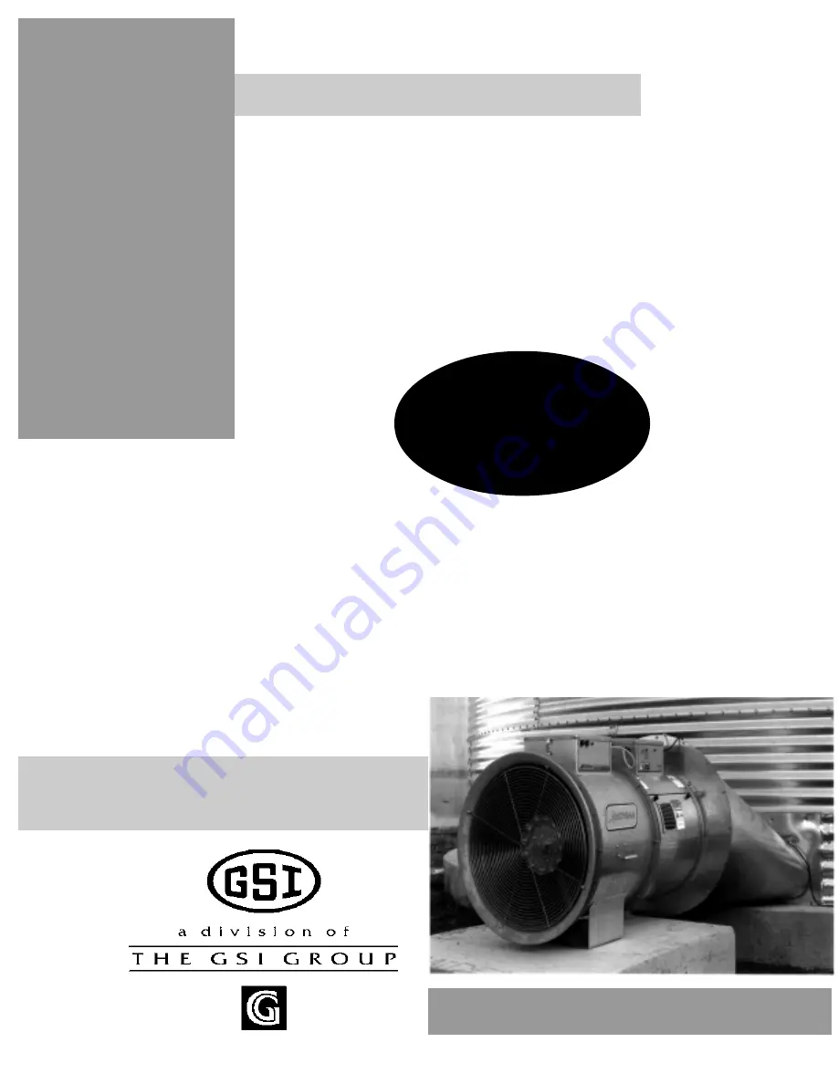
Fan And Heater

PNEG-377

Service

Manual

2 0 0 0

EDITION

Содержание PNEG-377

Страница 1: ...Fan And Heater PNEG 377 Service Manual 2 0 0 0 EDITION...

Страница 2: ......

Страница 3: ...2000 Centrifugal Fan Service Guide 17 2000 Gas Heater Service Guide 24 All Gas Heater Specifications 25 Series 2000 Heater 34 Deluxe Heater 52 Standard Heater 57 1996 1994 Gas Heaters 62 1993 1991 Ga...

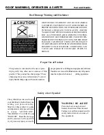
Страница 4: ...NAL PRESSURE FROM FANS OR OTHER AIR MOVING SYSTEMS ADEQUATE VENTILATION AND OR MAKEUP AIR DEVICES SHOULD BE PROVIDED FOR ALL POWERED AIR HANDLING SYSTEMS GSI DOES NOT RECOMMEND THE USE OF DOWN WARD FL...

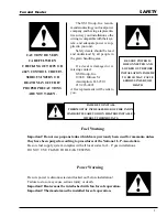
Страница 5: ...VERY CAREFUL WHEN CHECKING OUT 220V OR 460V CONTROL CIRCUIT SERIOUS INJURY OR DEATH MAY OCCUR IF PROPER PRECAUTIONS ARE NOT TAKEN BE SURE POWER IS DISCONNECTED AND LOCKED OUT BEFORE INSTALLATION FAILU...

Страница 6: ...6 Fan and Heater...

Страница 7: ...7 Fan and Heater 2000 VANE AXIAL FANS...

Страница 8: ...followingstepsensureproper ground rod installation 1 Dig a hole large enough to hold 1 to 2 gal lons of water 2 Fill hole with water Proper Installation of the Ground Rod 5 Connect the bare copper gro...

Страница 9: ...9 Fan and Heater TEST STATION...

Страница 10: ...10 10 15 14 12 12 12 5 10 14 14 12 12 5 10 3 3450 1 230 15 3 230 7 4 460 3 7 575 3 Copper Wire 12 10 8 6 12 12 10 8 14 12 12 10 14 12 12 10 Aluminum Wire 12 8 6 4 30 40 12 10 10 8 15 20 12 12 10 10 10...

Страница 11: ...NGTH 12 Dia 12 3 4 11 7 8 8 14 1 8 Figure 2 Fan dimensions 18 Dia 19 1 2 18 1 4 13 5 16 22 24 Dia 25 3 4 24 1 4 15 3 8 27 1 2 26 Dia 27 11 16 26 5 16 16 7 8 24 1 4 28 Dia 29 5 8 28 1 8 18 1 8 30 Note...

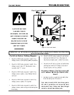
Страница 12: ...t of balance SOLUTION Replace fuses or reset breakers Turn power on at all disconnects ahead of the unit Follow wiring diagram and tighten any loose connections See wire size charts for proper sire si...

Страница 13: ...URY OR DEATH MAY OCCUR IF PROPER PRECAUTIONS ARE NOT TAKEN Figure 3 Fan circuit board 6 Check for 220V between points F and I while pressing start button If no voltage present checkout and replace sta...

Страница 14: ...14 Fan And Heater FAN WIRING AND SCHEMATIC Wiring 240 Volt 1 Phase 15 HP Schematic...

Страница 15: ...ested Relube Interval NEMAFRAME SIZE 254 to 326T 3 years 1 years 1 year beginning of season 6 months 364 to 447T 1 years 9 months 1 year beginning of season 3 months Lubricant Baldor motors are pre gr...

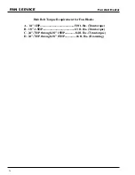
Страница 16: ...eater Hub Bolt Torque Requirement for Fan Blades FAN SERVICE A 14 1HP 50 ft lbs Trantorque B 18 1 5HP 63 ft lbs Trantorque C 24 7HP through 28 15HP 84 ft lbs Trantorque D 24 7HP through 28 15HP 16 ft...

Страница 17: ...17 Fan And Heater 2000 CENTRIFUGAL FAN SERVICE GUIDE...

Страница 18: ...5 7 8 92 1 16 D 24 7 8 27 3 8 27 3 8 30 30 33 1 2 33 1 2 36 1 2 36 1 2 33 1 2 E 25 1 4 27 3 4 27 3 4 30 3 16 30 3 16 32 15 16 32 15 16 33 3 8 33 3 8 32 15 16 Note All Dimensions in inches FAN 3HP 5HP...

Страница 19: ...4 4 2 2 60 60 8 8 6 4 30 30 8 8 6 4 30 30 FAN HORSEPOWER RPM PHASE VOLTS FULL LOAD AMPS MINIMUMWIRESIZE 50 RUN 100 RUN 200 RUN 300 RUN MINIMUMWIRESIZE 50 RUN 100 RUN 200 RUN 300 RUN FUSE SIZE SLOW BL...

Страница 20: ...Wire 6 6 4 2 6 6 4 3 10 10 8 6 10 10 8 6 Aluminum Wire 4 4 2 0 80 80 4 4 2 2 60 60 8 8 6 4 30 30 8 8 6 4 30 30 3500 RPM FAN SPECIFICATIONS 4 4 2 2 80 80 FAN HORSEPOWER RPM PHASE VOLTS FULL LOAD AMPS M...

Страница 21: ...21 Fan and Heater FAN SCHEMATIC AND WIRING 240 Volt 1 Phase 15 HP Marathon Schematic Wiring Diagram...

Страница 22: ...fans 254 to 326T 3 years 1 years 1 year beginning of season 6 months Suggested Relube Interval NEMAFRAME SIZE 42 to 215T 5 years 2 years 1 year beginning of season 6 months 364 to 447T 1 years 9 mont...

Страница 23: ...N SERVICE A 3 15HP 3500RPM fans 16ft lbs Browning B 20 50HP 3500RPM fans 29ft lbs Browning C 3 50HP 1750RPM fans 29ft lbs Browning D 3 7 5HP 1750RPM fans 125ft lbs Trantorque E 10 20HP 1750RPM fans 16...

Страница 24: ...24 Fan and Heater 2000 Gas Heater Service Guide...

Страница 25: ...USED AS A REFERENCE FOR SETTING MAXIMUM PLENUM TEMPERATURE FOR SAFE OPERATION P M E T O L H C T A B H G I H P M E T Y R D H C T A B G N I R R I T S O N H G I H P M E T H T I W G N I R R I T S S U O U...

Страница 26: ...o install onto HF 7318 board 4 Install HF 7318 into Snap track 5 Snap terminal strip tops back onto new circuit board 6 RemoveResetswitchfromfrontpanelofcontrolBoxandunwireleadsfromterminalstrip 7 Dri...

Страница 27: ...26 26 5 16 27 15 16 22 1 4 2700000 115 30 7 32 2 20 3 8 1128 7 32 2 20 3 4 2842 23 64 1 7 1 1 4 28 28 1 8 29 5 8 25 1 4 3000000 140 34 15 64 2 20 3 8 1253 15 64 2 20 3 4 3157 3 8 1 7 1 1 4 High Temper...

Страница 28: ...9 4 16 14 10 8 4 180 9 6 3 17 11 4 3 26 22 11 8 18 16 13 11 5 20 18 13 10 5 Gauge Pressure Psi Required To Maintain Temperature Approximate HIGH TEMP UNITS ONLY 2 102900 148370 Diameter 18 24 28 4 145...

Страница 29: ...08260 2 205200 251710 1 144100 177840 Operating Pressure PSI Diameter 18 24 28 60 1 1 low temp 1 1 low temp low temp 2 1 1 low temp 1 1 1 1 low temp 1 1 1 1 low temp Fan Model 3HP 18 7HP 24 10HP 24 15...

Страница 30: ...e Minimum line size Maximum fuel flow CFH Orifice Minimum operating pressure Minimum operating pressure Minimum line size Inside diameter Bolt circle diameter length BTU rating Weight Vapor Models Nat...

Страница 31: ...1 2 2 2 2 2 1 1 low temp 3 2 2 1 3 2 2 1 low temp Static Pressure 2 3 4 5 2 3 4 5 3 4 5 6 3 4 5 6 3 4 5 6 3 4 5 6 5 Fan Model 10HP 15HP 20HP 25HP 30HP 40HP Heat Rise Degrees F 30 2 2 2 2 3 2 2 2 4 3...

Страница 32: ...0 3 275 000 4 317 000 5 354 000 6 388 000 7 420 000 8 449 000 Gauge Pressure Psi Required To Maintain Temperature Approximate 20 1 1 1 1 1 1 1 1 1 1 1 1 2 2 2 1 2 2 2 1 3 2 2 2 Static Pressure 2 3 4 5...

Страница 33: ...Maximum operating pressure Minimum line size Maximum fuel flow CFH Orifice size Minimum operating pressure Maximum operating pressure Minimum line size Hi Temp Model 4000000 145 43 25 3 30 3 8 1590 25...

Страница 34: ...5 8 or larger to accommodate mounting nut 3 Mount Box to Bin using 4 self drilling screws 4 Caulkbetweenhousingandside walltoseal Air Switch Box Assembly 1 Mark location on transition one 1 foot up fr...

Страница 35: ...ter Unit 4 Third heater unit may also be added to system If adding third unit run connections to master unit 1 and connect them in parallel with sec ondary heater unit 2 Run 2 20 gauge minimum wires f...

Страница 36: ...ee Figure A 2 Using sensor as a guide drill or knock out 7 8 diameter hole in the center of the plenum on the bin sidewall If you are using sensor to sense drying air humidity 3 Insert pipe nipple fro...

Страница 37: ...instal lations Power Up the controller locks up with the main display alternating between a FAN and ON message This may be bypassed by depressing and holding the FAN BYPASS switch lower right switch...

Страница 38: ...ondition illuminated see section on Running the Dryer for mode explanation on page 17 The main display shows the plenum temperature If the dryer has not been running the display should show outside te...

Страница 39: ...er unit 11 Start the fan unit 12 Make sure that the blade is spinning in the right direction If not place the toggle switch in the OFF position and correct the problem 13 After the fan reaches full sp...

Страница 40: ...e pressure gauges should be set at 10 15 lbs for LP units or 4 6 lbs for natural gas units use the charts on the following pages to set pressure 19 Open or close the low cycle ball valve until the gas...

Страница 41: ...red low 3 With heater on and fan off display on heater should read no airflow 4 Start fan Heater display should now read airflow 5 If display does not read airflow remove cap from adjustment port and...

Страница 42: ...he hi lo flame temperature If the tempera tureisabovethehightemperatureset ting theflamewillbeoff the FLAME message will be out and the display willbeflashing OFF CYCLE If the flame is shut off becaus...

Страница 43: ...h again will cause the new setting to be entered into memory and the display will ad vance to the next function to be pro grammed Programming may be done at anytime unless an error condi tion exists e...

Страница 44: ...grain depress and hold the SHUTDOWN HOURS switch While holding in on that switch depress the START switch After depressing the start switch one time the heater is in the shutdown mode Then the fan an...

Страница 45: ...ple numtemperaturetoequalize Whenthetempera tureunderthebinhasequalized graduallyturn T handlein clockwise about1 2turnatatime desiredtemperature continueturningT handle in increasinggasflowandwaiting...

Страница 46: ...n all others off Slave 1 dip switch one and three on all others off Master with two slaves dip switch 8 on all others off Slave 2 dip switch two and three on all others off Master with 3 slaves dip sw...

Страница 47: ...7 8 9 10 11 12 Misc Error Numbers and the RX TX symbolswillbe flashing If a limit switch error or one of the error numbers 1 through 8 occurs that error is displayed on the slave where the error orig...

Страница 48: ...ctions Replace any damaged wiring 2 Remove burner orifice tube and inspect for dirt or foreign material Clean out if necessary 3 Inspect burner for wear or foreign material in any of the ports Cleanor...

Страница 49: ...49 Fan and Heater WIRING DIAGRAM...

Страница 50: ...cate programming jack P7 on back of computer See page 72 3 Plug the series 2000 cable into programming jack and into programmers DB 9 jack 4 Be sure that the rotary switch on the programmer is set to...

Страница 51: ...1 72 83 7 62 7 5 21 3520 3 8 352 5 00 5 172 7 6 5 6 2 0 3 2 5 7 6 2 1 3 6 7 8 5 1 5 2 2 2 5 2 1 2 2 1 3 6 7 1 2 2 8 5 1 2 5 7 2 1 3 6 7 0 5 1 2 2 1 0 2 3 6 7 5 6 7 7 6 7 2 1 2 5 2 3 6 7 6 021 725 1 6...

Страница 52: ...onnection of wires in fan box as shown in Figure 2 110V power supply or 5KVA 460V to 110V transformer must be used to supply power for heater IM PORTANT HEATER MUST BE INTERLOCKED WITH FAN FOR SAFE OP...

Страница 53: ...stat is the 4 x 4 white box with knob that is preconnected to heater when heater is ordered with thermostat 1 24 to the right side of the transition drill one 3 8 hole high temp or 1 1 2 hole low temp...

Страница 54: ...nd inspect all com ponents for moisture vibration or redent damage Inspect and tighten all loose terminal connections Replace any damaged wiring 2 Remove burner orifice tube and inspect for dirt or fo...

Страница 55: ...3 Connect wire between term 13 on relay base and terminals 8 on circuit board in master heater 4 Run 2 wires 18 gage between master and slave heaters 5 Connect wires to terminal 5 and 9 points A and...

Страница 56: ...56 Fan and Heater WIRING SCHEMATIC...

Страница 57: ...57 Fan and Heater STANDARD HEATER WIRING...

Страница 58: ...58 Fan and Heater STANDARD HEATER SCHEMATIC...

Страница 59: ...s use voltmeter to check between termi nals that are designated not between terminals and ground Voltage terms 1 and 8 Check incoming power supply to heater Voltage terms 2 and 8 Fuse blown or on off...

Страница 60: ...LQ IODPH ODPH SUREH FRQWDFWV VKRXOG RSHQ ZKHQ SUREH JHWV KRW QFRUUHFW 6XSSO 9ROWDJH 9ROWDJH WR KHDWHU PXVW EH YROWV 5HJXODWRU VHW WR ORZ 6HH WKDW IODPH EXUQV FRQWLQXRXV DQG LV QRW LQWHUPLWWHQW 2Q ULQJ...

Страница 61: ...61 Fan and Heater NOTES Notes...

Страница 62: ...62 Fan And Heater 1996 1994 Gas Heaters...

Страница 63: ...63 Fan And Heater DELUXE HEATER WIRING...

Страница 64: ...64 Fan And Heater DELUXE HEATER SCHEMATIC...

Страница 65: ...65 Fan And Heater DELUXE HEATER SCHEMATIC 1993 1995 Heaters...

Страница 66: ...eater 3 Connect other end of these wires to termi nals 4 and 5 Points F and E on lower left hand corner of HF 7100 board in 2nd heater Installation HI LO Units 1 Plug 1 TD 100282 Relay into empty sock...

Страница 67: ...me and goes out when switching to low flame When the plenum chamber reaches the preset tem perature of the humidistat thermostat lights 1 and 2 will be lit all other lights will be out Once the flame...

Страница 68: ...ection is good replace flame detection module 1 2 and A If onlylights 1 2 and A are lit check the 10 second purge relay and or the DPDT relay Replace either part if faulty and restart unit 1 2 3 and A...

Страница 69: ...ncrements and allow bin time to even out Always try pivoting burner first this works great for minor adjustments Thermostat should always be mounted on right side of transition looking into bin as thi...

Страница 70: ...70 Fan and Heater 1991 1993 GAS HEATERS...

Страница 71: ...i nals 4 and 5 Points F and E on lower left hand corner of HF 7100 board in 2nd heater Installation HI LO Units 1 Plug 1 TD 100282 Relay into empty socket on HF 7100 Control board in Main heater 2 Ins...

Страница 72: ...72 Fan And Heater WIRING SCHEMATIC 1991 1992 Heaters...

Страница 73: ...73 Fan and Heater 1990 GAS HEATERS...

Страница 74: ...CLOSED FOR UNIT TO START Check voltage between points A and B If 110 volts is present then flame probe is probably OK If no voltage present check between points B and C If 110 volts present flame prob...

Страница 75: ...nd F on lower left hand corner of HF 7062 board in 2nd heater or install 2 prong plug on wires and plug into front of control box in receptacle marked CYCLE Installation HI LO Units 1 Plug 2 TD 100282...

Страница 76: ...76 Fan and Heater PRE 1990 GAS HEATERS...

Страница 77: ...77 Fan and Heater HEATER WIRING DIAGRAM...

Страница 78: ...78 Fan and Heater HEATER SCHEMATIC Vane Axial LP Heater...

Страница 79: ...79 Fan and Heater HEATER SCHEMATIC Vane Axial Vapor Heater...

Страница 80: ...80 Fan and Heater HEATER SCHEMATIC Downwind LP Heater...

Страница 81: ...81 Fan and Heater HEATER SCHEMATIC Downwind Vapor Heater...

Страница 82: ...82 Fan and Heater HEATER SCHEMATIC Lo Fire Downwind Heater...

Страница 83: ...83 Fan and Heater MISCELLANEOUS INFORMATION...

Страница 84: ...ay contacts that replace the mechanical flame probe The blue black wire is the common thewhite brownwireisthe normallyclosed andthewhite blueis thenormallyopen OnallAirstream heaters use the blue blac...

Страница 85: ...me probe The blue black wire is the common thewhite brownwireisthe normallyclosed andthewhite blueis thenormallyopen OnallAirstream heaters use the blue black and the white brownwires Thewhite blue wi...

Страница 86: ...eisthe normallyclosed andthewhite blueis thenormallyopen OnallAirstream heaters use the blue black and the white brownwires Thewhite blue wire should be used only on makes of heaters that use a normal...

Страница 87: ...ct vaporizer They should not be used as a expansion valves handling liquid LP on straight liquid withdrawal systems A pressure regulating valve is required to maintain uniform inlet pressure to the V5...

Страница 88: ...down This allows the temperature sensing element to perform properly In vapor withdrawal systems the gas flowing through the valve is cooler than the sensing bulb and valve is cooler thatn the sensing...

Страница 89: ...erating cycles to be sure that all components are functioning correctly Gas pres sure through the valve should be verified by an accurate gage Repairs and Replacement The internal parts orifice plug d...

Страница 90: ...ame until the end of the duty cycle Should a flame out occur during the duty cycle the system will reactivate the spark with 0 8 seconds to provide for re ignition The flame will either be re establis...

Страница 91: ...electrode lead wires to the control module See Figure 3 Make certain that the remaining system wiring is complete 4 With the gas supply m anually shut off cycle the thermostat to operate the control...

Страница 92: ...r all connections When making connections be Warning Do not apply power to imput terminals unless electrode is properly connected and grounded or damage to the unit may result System Checks Preliminar...

Страница 93: ...93 Fan and Heater FENWAL SERIES 05 14 Figure 2 Figure 3...

Страница 94: ...ually shut off the gas supply and apply power to the control board After the trial for ignition period has elapsed check that there is no voltage output between terminals B V1 and V2 using a suitable...

Страница 95: ...and ship repaid FENWALINCORPORATEDDivisionofKiddeInc K I D D E 400MainStreetAshland Massachusetts01721 617 881 2000 5 14 125M11 86PrintedinU S A W W GRAINGER INC Distribution Group 5959 W Howard St C...

Страница 96: ...5 3 9 1 1785 3 9 1 1785 3 9 1 1785 3 9 1 25 SUHVHQW 3 9 1 25 SUHVHQW 3 9 1 25 SUHVHQW 3 9 1 25 SUH 3 9 1 25 SUH 3 9 1 25 SUH 3 9 1 25 3 9 1 25 3 9 1 25 3 9 1 621 3 9 1 621 3 530 175 8 25 3 530 175 8 2...

Страница 97: ...97 Fan And Heater...

Страница 98: ...1004 E Illinois St Assumption IL 62510 Phone 217 226 4421 Fax 217 226 4498 February 2000...


Отзывы: