12V
Example: To Change the Engineer Code to 1234
Changing Engineer Code
Code Description
4 Changing the Engineer Code
Enter
Engineer
Code
+
+
1234
New Eng Code
Changing Settings
Code Description
6 Changing Backlight, Silent or Scan Mode
Example: To Toggle the Backlight to ‘Always On’ or ‘Only On after a Key
Press’
Example: To Toggle the Silent Operation On/Off
Example: To Toggle the Sensor Scanning Mode to Always On/Off
Note: If Sensor Scanning Mode is set to Off, the Red Sensor light will
be off in normal standby conditions and placing a finger on the sensor
window will not operate the Door Control.
To re-activate the Scan Sensor - press any key before placing the finger
on the Sensor window.
Enter
Engineer
Code
+
+
1
Enter
Engineer
Code
+
+
2
Enter
Engineer
Code
+
+
3
9
Operation Instructions
Code = 4
Amber LED flashes
Red LED flashes
Amber LED flashes
Code = 6
Code = 6
Code = 6
Amber LED flashes
Red LED flashes
Amber LED flashes
Amber LED flashes
Red LED flashes
Amber LED flashes
Amber LED flashes
Red LED flashes
Amber LED flashes
4
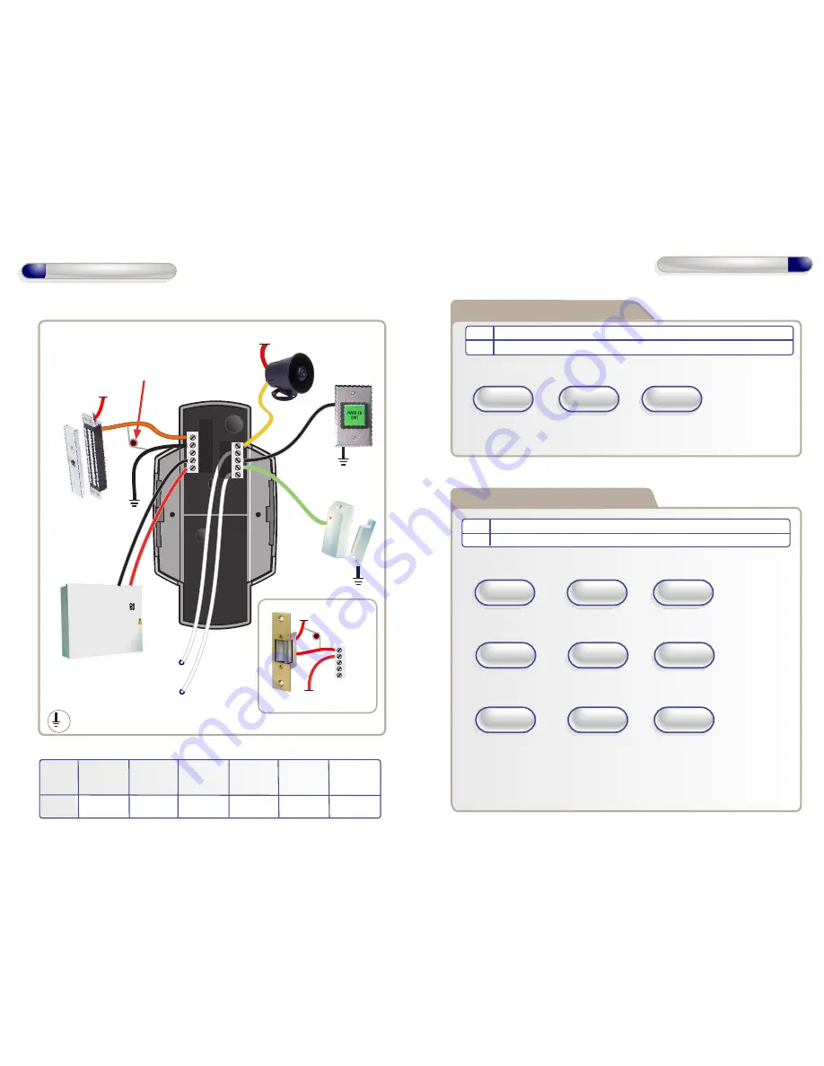
12V Linear
Power supply
Door
Contact
0V
Door
Exit Button
0V
Interlock OP to
Interlock IP on
2nd Door
Interlock IP from
Interlock OP on
2nd Door
12V
Sounder
Important:
Always fit the varistor supplied
with the unit between the
lock terminals as shown
NC
COM
NO
0V
12V
Door MagLock
Always connect a
varistor between a
solid ground OV and
the NC for a maglock.
Varistor
0V
Varistor
12 - 24 VAC
12 - 24 VAC
Wiring for StikeLock only using 12 - 24VAC supply
12V Linear
Power supply
Door
Contact
0V
Door
Exit Button
0V
Interlock OP to
Interlock IP on
2nd Door
Interlock IP from
Interlock OP on
2nd Door
12V
Sounder
Important:
Always fit the varistor supplied
with the unit between the
lock terminals as shown
NC
COM
NO
0V
12V
OP2
OP1
IP1
IP2
IP3
Wiring Diagrams
Default
Door Exit
Button
Door
Contact
Interlock
I/P
Table 1
Page 5
Input 1
Input 2
Input 3
Output 2
Output 1
Wiring
Diagrams
Alarm/
Buzzer
Interlock
O/P
Note: All OV shown in the diagram are connected
to OV at the back of the keypad terminal block.
0V
NC
COM
NO
0V
12V


