background image


68


Offset 

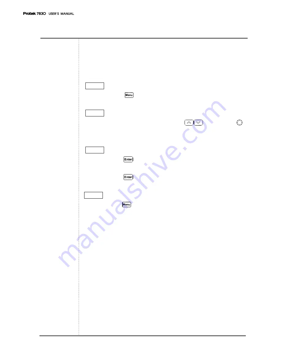
Level Offset compensates for any loss due to the cabling. 

Offset adds the value of +Offset to all the values of measurement. 


STEP 1 

- Press the 

Menu 

 key twice. 


STEP 2 

- Set the cursor on Offset using


the

 Up/Down 

 Keys or 

knob 


Key. 


STEP 3


- Push the

 Enter


  Key and then move to the submenu. 

- Input the dB value of Offset. 

- Push the

 Enter


 Key 


STEP 4 

- Push the

 Menu


Key once more to exit the system menu. 


Содержание Protek 7830

Страница 1: ...Protek 7830 Manual Get Pricing Availability at ApexWaves com Call Today 1 800 915 6216 Email sales apexwaves com https www apexwaves com analyzers protek protek analyzers 7830...

Страница 2: ...87 USER S MANUAL...

Страница 3: ...2 2 Update Spec Update Spec GS Instruments Co Ltd 1385 14 Juan 5Dong Nam Ku Incheon the Republic of Korea Tel 82 32 870 5637 5652 Fax 82 32 870 5640 E mail isale gsinstrument com Homepage http www gs...

Страница 4: ...dentifies conditions or practices that could result in injury or loss of life Caution symbol identifies conditions or practices that could result in damage or fire Ground symbol identifies conditions...

Страница 5: ...lt in damage to this instrument Also continually cleaning the dust on the input terminal of RF frequency counter Clean the input terminal regularly Dust could result in damage to the instrument RF in...

Страница 6: ...me Keep away from liquids Avoid high moisture and or poor ventilation Keep away from dust and or smoke Avoid extremely low temperature Battery Protek 7830 Ni MH battery is rechargeable Battery is rech...

Страница 7: ...entually need to replace Operating personnel should phase in a new battery when the battery running time is less than half hour The warranty period is 6 month after instrument use has begun Operating...

Страница 8: ...this instrument against specification Defect resulting from improper or inadequate maintenance by buyers Defect is caused by the environment such as fire flood or earthquake Buyer installs substitute...

Страница 9: ...essories Standard Option Carrying case AC Adaptor Carrying Strap Coaxial Cable RS 232 Cable Power Cable Earphones N BNC Adaptor Ni MH Rechargeable Battery 6PCS User s Manual X 2PCS Antenna GUI Softwar...

Страница 10: ...r Panel 20 Side Panel 21 Top Panel 22 5 Basic operation Before Power On 23 Power On 24 Turn on Power of Instrument 25 Description of operation screen 26 Reception Mode 32 Sweep Mode 33 Set up Span 34...

Страница 11: ...Run GHz 76 Mode MHz 76 Sweep kHz 77 Marker DEL 77 No 1 Start Stop 78 No 2 Span 78 No 3 Level 79 No 4 PK Search Peak Search 79 No 5 MKR to CNT Marker to Center 80 No 6 CH Power Channel Power 80 No 7 LC...

Страница 12: ...he Protek 7830 provides various functions and user friendly interfaces which make it easy for the users to check the location of the antenna with simple handling The Spectrum Analyzer is ideal for use...

Страница 13: ...on PLL tuning system for precise frequency tuning Built in Speaker 192 Pixels X 192 Pixels Back Light LCD Menu selection method for Function selection RS 232C Interface User friendly Icon Display Main...

Страница 14: ...ectable Squelch Function The Squelch Level may be adjusted to any value from the reference level to Full Scale Copy Function The Copy Set mode allows the contents of the Channels edit Setup and Data m...

Страница 15: ...Narrow FM 1MHz 2MHz Wide FM 1 20MHz Multiple of 1 MHz 20 400MHz Multiple of 20 MHz Frequency Selection Mode Center Start Stop Span Measurement Range 20 dBm to 110 dBm Average noise Level Wide FM 100 d...

Страница 16: ...z 150 mVrms 20 MHz to 1 000 MHz 100 mVrms 2 000 MHz to 2 900 MHz 400 mVrms Input Impedance 50 Ohms Max Input Voltage 5 Vrms Max Speed Min 500 msec Trigger Source Narrow FM Wide FM AM SSB Trigger Mode...

Страница 17: ...700 mAh Rechargeable Nickel Metal Hydride Battery Adapter SMPS Type AC Adapter DC 12 V Output Car Adapter DC 12 V Output Auto Power On Off Off 5 min 10 min 20 min 30 min The Protek 7830 can be quickl...

Страница 18: ...Type AC Adapter Fuji AA type NI MH Rechargeable Battery 6 PCS 1 2 V 2 700 mAh Manual Coaxial Cable Earphones Carrying Case Carrying Belt RS 232C Cable Adapter N BNC Software for PC Application Matchin...

Страница 19: ...alues and system data Power Key Key to turn ON OFF of the system Run Mode Sweep Marker Key Run Key to run the Scanning or input the GHz unit for frequency value input Instrument overview LCD Front Fig...

Страница 20: ...ncy value input Marker Key to select the Marker Function Marker Delta Marker Squelch Marker Peak Search Marker to Center and Channel Power Numeric Key Key to input the frequency value Menu Key Key to...

Страница 21: ...r to output the modulated audio from RF signal level Reset Key Users can use this Reset key from system s malfunction or memory reset Battery Note the polarity of batteries at inserted battery compart...

Страница 22: ...use this DC input jack for power supply and battery charging with SMPS type AC DC Adapter or Car Adapter RS 232C Connector 8 pin mini DIN connector Users can use the RS 232C connector for PC communica...

Страница 23: ...put voltage is 5 Vrms Input Connector for Frequency Counter Users can connect the signal source to this connector as an input The maximum input voltage is 5 Vrms Volume Control Users can control the v...

Страница 24: ...m the battery icon on the display window is displayed and blinking And if the charging of batteries is finished the blanking of battery icon will stop and only be displayed To measure the input level...

Страница 25: ...This system supports shortcuts with the combination of keys To use this shortcut function press the key and press the numerical key The frequently used function description is marked on the numerical...

Страница 26: ...t to LCD Contrast Push the Key Push the LCD CONTRAST No 8 Key Adjust to desired LCD Contrast using the Up Down Keys or Knob Key STEP 3 Push the Dot Key to be taken out of Menu STEP 4 LCD Light On Off...

Страница 27: ...26 Description of operating screen 1 ICON window 2 Frequency Input window 3 Wavy pattern window 4 Squelch window 5 Marker window 1 ICON window...

Страница 28: ...odulation Mode Sweep Mode State Indication Free Run Squelch Run Single Run Run Scanning Run Stop State Indication Running Stop Marker State Indication None Center Marker State Marker 1 State Delta Mar...

Страница 29: ...28 Description of operating screen Buzzer On off Indication Buzzer Off Buzzer On Battery Residual Indication Full Empty LEVEL ATTN 2 Frequency Input window Icons are changed by Dot Buzzer key...

Страница 30: ...ndication of Frequency Value of each Mode Level Value Indication Indication of Level Value of each Mode Level Unit Can be selectable in the main menu Please refer to Menu Level Unit establishment for...

Страница 31: ...o Vertical Level Value of Wavy pattern window Please refer to screen level establishment in basic operations for further details Resolution of Screen Level Value Marker Indication Center Marker Every...

Страница 32: ...nter Frequency MHz SPAN Span Frequency STEP Step Frequency When Delta Marker MKR1 Marker 1 Frequency MHz LEV1 Marker 2 Level Value dBm DIFF Marker1 Marker2 Level Value When Measuring Channel Power CEN...

Страница 33: ...gnal of bandwidth the Narrow FM mode is used to interpret a narrow Bandwidth Signal AM and SSB can be used irrespective of Bandwidth Push Mode MHz Key to establish the reception mode and then the top...

Страница 34: ...p Run Scanning in case of the signal level value is getting higher than the squelch level value But If the signal level is getting lower than the squelch level restart to Run Scanning After input is f...

Страница 35: ...tomatically Example If Span Input is 50 MHz it would automatically be set at 60 MHz First push the Shift Key in order to set up Span Then the top left ICON is changed to After that push the No 2 Key S...

Страница 36: ...Then push the No 1 Start Stop Key to input Start Frequency in Frequency Input Window Input Frequency by using the No 0 to 9 Keys Dot Buzzer Key MARKER DEL Key and Run GHz as Unit Input Key Mode MHz a...

Страница 37: ...the Shift Key STEP 2 Push the No 1 Key STEP 3 Make sure that Frequency Input Window is changed to Start Input Mode Input a desired Frequency to use the numeral keys and the Dot Key STEP 4 Input a unit...

Страница 38: ...ng the Enter Key Top Level in the vertical axis would be changed to be established Value DIFF is an abbreviation of Difference Choose through the Up Down Keys and establish to use the Enter Key Level...

Страница 39: ...38 Run Scanning Run Scanning is a process interpreting Frequency according to established Frequency Bandwidth and Span And Run scanning processes operates by established Sweep Modes...

Страница 40: ...ker ICON Remarks Center Marker No ICON Center Marker Marker 1 Users can move Marker 1 to the desired position Marker 2 Users can move Marker1 or Marker 2 to the desired position Users can see the diff...

Страница 41: ...ect when using Mark Mode in the basic operations When inputting Start Frequency and Stop Frequency Center Frequency the information will appear automatically Frequency and Level on Center Frequency wi...

Страница 42: ...r 1 To move the Marker 1 use the Up Down keys or the Knob key Then the frequency value and level value are displayed on frequency input window STEP 1 Press the Marker DEL Key Check the Marker 1 mode i...

Страница 43: ...Delta Maker Squelch Marker When users set up the Delta Marker the frequency value and level value of Marker 2 are displayed in the frequency input window The frequency value and level value of Marker...

Страница 44: ...the Up Down keys or Knob key Then the frequency value and level value of Marker 2 are displayed in the frequency input window The frequency value and level value of Marker 1 and the difference level...

Страница 45: ...the Squelch Level of Sweep mode and speaker output for a larger signal than Squelch Level through modulation for audio frequency ranges Modulation Frequency modulation Amplitude modulation and SSB Mo...

Страница 46: ...STEP 1 Press the Marker key Check the Squelch Marker mode STEP 2 Move the Squelch Marker to the desired point using the Up Down Keys or Knob Key The squelch value is displayed in the lower right displ...

Страница 47: ...rker 1 are displayed in the display window The Marker mode is the total four modes and the changing order of Marker mode is as below Center Marker 1 Delta Maker Squelch Marker Move the Marker 1 to the...

Страница 48: ...e display window STEP 2 Press the Shift key STEP 3 Press the No 4 PK Search key Then the Marker 1 is moved to the peak point and the frequency value and level value are displayed in the frequency inpu...

Страница 49: ...n must be run in Marker 1 mode Press the Shift key to change the upper right icon to And press the No 5 Marker to CNT Key Then the Marker 1 position will be in the center of the display window Center...

Страница 50: ...to the desired point using the Up Down Keys or Knob Key STEP 3 Run the function for Peak Search by pushing Shift No 4 Make sure that the marker is located on the peak signal STEP 4 Press the Shift key...

Страница 51: ...lay shows the illustration of the channel power measurements The default channel power bandwidth is the half of the span size In this mode the span size can be adjustable by pushing Shift No 2 SPAN In...

Страница 52: ...n Marker in the main menu STEP 2 Input the center frequency STEP 3 Move the Marker to select the desired channel power ranges using the Up Down Keys or Knob Key STEP 4 To be out of this mode Press the...

Страница 53: ...with Menu function To set the internal attenuator press the Shift key to change the upper right icon to And press the No 9 ATTN key To adjust the value of internal attenuator press the Up Down Keys or...

Страница 54: ...a dark location Press the Shift key to change the upper right icon to And press the No 7 LCD Light key The Power ON OFF of the LCD Light will toggle STEP 1 Press the Shift key STEP 2 Press the No 7 LC...

Страница 55: ...key to change the upper right icon to And press the No 8 LCD Contrast key The LCD contrast is adjusted by using the Up Down keys or Knob key And press the Enter key STEP 1 Press the Shift key STEP 2 P...

Страница 56: ...r ON OFF User can set the Buzzer ON OFF Toggle ON OFF Press the Shift Key Then the Icon of left upper window is changed to shift icon And press the Dot Key STEP 1 Press the Shift key STEP 2 Press the...

Страница 57: ...y range Step value and Span value User can use this with Menu or Multi key The function of Load is for loading the saved Waveform and Setup Status in memory If user only wants the Setup Status please...

Страница 58: ...e Marker key STEP 5 When all 7 characters included blank are typed press the Enter key Then output message for SAVE OK is displayed SAVE OK If user does not type the all 7 characters included blank th...

Страница 59: ...ilename to retrieve To select the first character Use the Up Down keys And press the Enter key The function of Load is to load the saved waveform and setup status If user only wants to load only setup...

Страница 60: ...e Up Down keys or Knob key and press the Enter key STEP 3 To delete the saved data select the user s saved data using the Up Down keys or Knob key And press the Enter key Then the saved data will be d...

Страница 61: ...r the frequency counter is BNC connector When the input level is inputted into the Frequency Counter the measured frequency value is displayed in the frequency input window Input level is as below 9 M...

Страница 62: ...key and press the Enter key STEP 4 The icon is displayed from the other icon The FCNT is displayed in the frequency input window STEP 5 When the input level is inputted in the Frequency Counter using...

Страница 63: ...eck the battery s remained capacity Battery users can refer to the battery icon on the upper area of the display window How to use and replace the battery Please refer to the batter section in details...

Страница 64: ...et up as below dBm dBuV dBmV STEP 1 Press the Menu key STEP 2 To select the LEVEL UNIT use the Up Down keys or Knob key and press the Enter key Then sub menu is opened STEP 3 To select the user s want...

Страница 65: ...Cleared System INIT The upper two resets PRESET and MEMORY CLR are run Then system reboot for initial setup status and the user s saved data will be cleared STEP 1 Press the Menu key STEP 2 To select...

Страница 66: ...1 Press the Menu key STEP 2 To select the BAUD RATE use the Up Down keys or Knob key and press the Enter key Then sub menu is opened STEP 3 To select the baud rate value users want use the Up Down ke...

Страница 67: ...PC on the main menu 3 Run 7830 GUI Program on the PC STEP 1 Press the Menu key STEP 2 To select the CONNECT PC use the Up Down keys or Knob key and press the Enter key Then sub menu is opened STEP 3...

Страница 68: ...ly based on the time users select The auto power OFF time is same as below NONE 05MINUTES 10MINUTES 20MINUTES 30MINUTES STEP 1 Press the Menu key twice STEP 2 To select the AUTO POWER use the Up Down...

Страница 69: ...et to all the values of measurement STEP 1 Press the Menu key twice STEP 2 Set the cursor on Offset using the Up Down Keys or knob Key STEP 3 Push the Enter Key and then move to the submenu Input the...

Страница 70: ...ough the Menu The functions that can be selected in the main menu mode are as below To exit from Menu or System push the Menu Key or push the Dot key These keys will move users to the menu items eithe...

Страница 71: ...s want use the Up Down Keys or the Knob Key STEP 3 Push the Enter Key STEP 4 After selecting function of sub items or On Off push the Enter Key STEP 5 Exit the Menu after pushing the Menu Key twice Wh...

Страница 72: ...Run Set up the Sweep Mode The mode can be set up with the Shift Key Squelch Run Single Run Marker None Marker or function using the Marker The mode can be set up with the Shift Key Marker Delta MKR S...

Страница 73: ...CLR Delete the stored data System INI All Reset restarting the system and delete the stored data Band Rate 115 200 BPS Select the speed of serial communication between the unit and PC 57 600 BPS 38 4...

Страница 74: ...other keys Also the functions can be selected from main Menu and System Menu To exit from Menu or System push the Key or push the Dot key this will move users up to higher menu items in the tree stru...

Страница 75: ...for the System Menu Go to Step3 STEP 2 Press the Menu Key once more STEP 3 To select desired function use the Up Down Keys or the Knob Key STEP 4 Press the Enter Key STEP 5 After selecting a lower ite...

Страница 76: ...s Buzzer ON Select Buzzer On Off OFF LCD Light ON Select LCD Light On Off OFF LCD Contrast 1 to 10 Step INT Atten 0 dB 10 dB 20 dB 30 dB 35 dB Offset 99 0 dB to 99 0 dB Default save SAVE During bootin...

Страница 77: ...a unit GHz to input Start Stop Scan Center frequencies After inputting the frequency values push this key to add a unit of GHz Mode MHz Selecting Reception Mode The following Reception Modes can be s...

Страница 78: ...ue of frequencies push this key to add a unit of kHz Marker DEL Selecting Marker functions After pushing this button please select Marker functions such as Center Marker Marker 1 Delta Marker and Sque...

Страница 79: ...de by pushing the Shift Key and than push the numeral Key Please refer to the Frequency Input section for basic operations No 2 Span Push the No 2 key to input the value of 2 To input the value of num...

Страница 80: ...Please refer to the Display Level Adjustment section for detailed basic operations if need No 4 PK Search Peak Search Push the No 4 key to input the value of 4 Use the No 4 Key to input the value of n...

Страница 81: ...e selected Please refer to the Marker to Center section for detailed descriptions for using the Marker Function if needed No 6 CH Power Channel Power Push the No 6 key to input the value of 6 The No 6...

Страница 82: ...ned on or off Please refer to the LCD Light section for details about basic operations if needed No 8 LCD CONT LCD Contrast Push the No 8 key to input the value of 8 To input the value of numeral 8 in...

Страница 83: ...lect the level of an internal attenuator Please refer to the Attenuator Setup section for details about basic operations No 0 System Push the No 0 key to input the value of 0 When inputting the value...

Страница 84: ...The Dot key is used to input a decimal point When inputting the value of Decimal Point in the Start Stop Scan Center frequencies this key is used Buzzer Setup Function after pushing the Shift Key By p...

Страница 85: ...the Shift Key By pushing the Shift key and the Menu Key stored data are loaded after selecting a file on the list Please refer to the Store Mode section for details of basic operation Enter Save Enter...

Страница 86: ...85 Up Down Keys and Knob Key Up Down Keys and Knob Key Functions Up Down keys and knob are used for the movement of markers and menu system items...

Страница 87: ...86...

Страница 88: ...ng function 3 Specification Item Specifications Frequency Range 30MHz 2 9GHz Amplitude Measurement Range 55dBm 65dBm 5dB steps Amplitude Units DBm Level Accuracy 2 0dB Typical 95 20 30 3 0dB Other 5 2...

Страница 89: ...0 Level Setting Procedure 1 Connect cable between G632 and 7830 2 Signal generated from G632 at 60dBm 3 Check 7830 Level 4 Level difference between 60dBm and 7830 can be compensated from offset menu i...

Страница 90: ...Measuring Device 900MHz Band Pass Filter C Test Block Diagram Test Results A 7830 Output Signal Level 61 70dBm B Path Loss G632 7830 1 5dB 1 Band Pass Filter 1 4dB 2 Cable Loss 0 1dB C 7830 LCD Displa...

Страница 91: ...2 to 7830 A Fix Int Atten Fix INT Atten of 7830 to 20 dB when connecting with G632 B Ext Atten Ext Atten of 7830 disabled when connecting with G632 C 7830 Mode Change Changing Mode disabled when conne...

Отзывы: