background image

Mechanical installation

5.1 Regular requirements

Make sure that module installation mode and bracket system are solid enough to
bear the expected load, which is requisite assurance that the bracket installer must
provide. Installation bracket system shall be tested and inspected by the third
party testing institution with static mechanical analysis capacity in accordance
with local national or international standards.

Module bracket shall be made from durable, corrosion resistant, ultraviolet proof
materials. Modules shall be fixed on the bracket solidly.

Use higher brackets in places with heavy snow accumulation so the lowest point of
modules will not be covered by snow for a long time. In addition, make the lowest
point high enough so as to avoid sheltering of vegetations and woods or damage
of flying sands and stones.

If modules are installed on brackets parallel to the roof or wall, the minimum gap
between the module frame and the roof/wall shall be 10cm for air ventilation so as
to prevent module line damage.
Do not make holes on glass or frame of modules.
Make sure the building is suitable for installation before installing modules on roof.
Moreover, seal permeable parts properly to prevent leakage.
The module frame has thermal expansion and cold contraction so the frame
interval between two adjoining modules shall be less than 10mm.

Make sure that back plate of modules will not contact bracket into the module or
building structures, especially when the module surface is imposed by pressure.

GRUPPOSTG Solar Modules have been certified for a maximum design static load
on the back of the Modules of up to 1600Pa*1.5 (i.e. wind load) and a maximum
design static load on the front of the Modules of up to 3600Pa*1.5 (i.e. wind and
snow load), depending on the clamp mounting (please refer to follow installing
data for this information). And this is printed on the label of modules.

Module installation methods can not lead to electrochemical corrosion between
module aluminum frame and different metals. Electrochemical potential
difference of contacting metals shall not exceed 0.6V as is recommended in UL1703
Appendix Flat Plate Photovoltaic Modules and Panels.
Modules can be installed horizontally or vertically.

Installation Manual PV Modules High Power Half Cut

8

Содержание SOLARGREEN VE4 PV Series

Страница 1: ...o as GRUPPOSTG Please abide by all safety precautions in this guide and local regulations Installation of modules requires professional skills and knowledge and is to be carried out by qualified perso...

Страница 2: ...uirements 5 2 Way of installation 8 8 9 Electric installation 6 11 6 1 Electric performance 6 2 Cables and connecting lines 11 13 6 3 Connector 13 6 4 Bypass diode 14 Grounding 7 14 3 7 1 Grounding by...

Страница 3: ...l to install modules as per requirements set forth in this manual the quality warranty provided for customers during sales will become invalid In addition suggestions in this manual are to improve saf...

Страница 4: ...llation Manual PV Modules High Power Half Cut 4 GRUPPOSTG module is considered to be in compliance with UL 1703 only when the module is mounted in the manner specified by the mounting instructions bel...

Страница 5: ...ng environments will intensify light reflection and lead to increase of current and output power And module voltage and power will increase under low temperature If module glass or packaging materials...

Страница 6: ...n building fire protection Fire rating of GRUPPOSTG modules is Type4 according to UL 1703 The roof shall be coated with a layer of fireproof materials of such rating for roofing installation and make...

Страница 7: ...as air pollution and soot or in places with strong corrosive substances such as salt salt mist saline active chemical steam acid rain or other substances corroding modules affecting module safety or p...

Страница 8: ...s on glass or frame of modules Make sure the building is suitable for installation before installing modules on roof Moreover seal permeable parts properly to prevent leakage The module frame has ther...

Страница 9: ...the support profiles using metal clamps The following clamps or those clamps recognized by module system installer are recommended Width no less than 40mm Thickness no less than 3mm Material aluminum...

Страница 10: ...Clamp A for tail end module edge Clamp B for middle modules Figure 3 Clamp Illustration unit mm Installation Manual PV Modules High Power Half Cut 10 3 0...

Страница 11: ...or with those under standard testing conditions of irradiance of 1000 W m2 cell temperature of 25 C and air mass of AM1 5 Under normal conditions a photovoltaic module is likely to experience conditio...

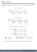
Страница 12: ...models can not be connected in one series Serial connection Parallel connection Parallel connection after series connection Figure 5 Series connection and parallel connection circuit diagram Installat...

Страница 13: ...ve level of IP68 These designs facilitate parallel connection of modules Each module has two independent wires connecting the connecting box one is negative pole and the other is positive pole Two mod...

Страница 14: ...UPPOSTG suggests that DC negative pole of the module array shall be grounded in installation of modules Otherwise the system power output will be reduced Module installation methods can not lead to el...

Страница 15: ...structions provided with the module Grounding methods below are permissible 7 1 Grounding by grounding clamp There is a grounding hole with the diameter of 4 2mm at the edge of the module back frame T...

Страница 16: ...hole Use grounding bolt to go through the grounding clamp and frame 2 Put the tooth side of the washer on the other side and fasten the nuts The recommended torque for nut fastening is 2 0Nm to 2 2Nm...

Страница 17: ...7 Installation Manual PV Modules High Power Half Cut 8 1 Cleaning Accumulated dust on module surface glass will reduce the power output and lead to local heat spot such as industrial waste water and b...
Страница 18: ...moisture into the module due to damage of surface packaging materials during installation or transportation Check whether there is burning traces on the module back plate Check module appearance defe...

Страница 19: ...ono Si Mono Si Mono Si Mono Si Number of cells 144 132 120 108 Rated short cirtuit current range A 13 56 13 65 13 74 13 83 13 92 13 46 13 55 13 64 13 73 13 82 13 56 13 65 13 74 13 83 13 58 13 67 13 76...

Страница 20: ...Rated current at Pmax range A 20 20 20 Rated voltage at Pmax range V 1500 1500 1500 Maximum system voltage VDC UL1500 UL1500 UL1500 Over current protection rating A 20 20 20 Dimensions l x w x h mm 2...

Отзывы: