GRUNDIG Service
2 - 2
CUC 7301 F
Description des circuits / Circuit Description
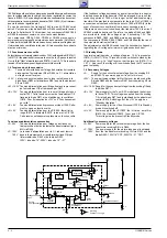
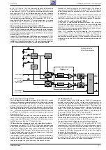
Internal
Bias
Reference
Regulator
Oscillator
1.0mA
Error
Amplifier
+
-
+
-
2R
R
1.0V
Current Sense
Compartator
Gnd
5
Output
Compensation
1
2
Voltage Feedback
Input
4
8
R T
Vref
R
R
2.5V
3.6V
Vref
UVLO
Vcc
UVLO
Vcc
7
36V
Vcc
Vin
Vc
Output
Power Ground
Current Sense Input
7
6
5
3
Rs
T665
R
S
Q
PWM
Latch
+
-
+
-
=
Sink Only
Positive True Logic
C T
T665 s'allonge et de ce fait une plus grande quantité d'énergie est transmise
pour la compensation de la charge. L'entrée de régulation du courant se
trouve à l'IC630-(3). En cas d'augmentation de consommation de courant
côté secondaire, la commande du transistor T665, IC630-(6), est interrom-
pue via l'entrée de régulation pin 3.
En cas de court-circuit du transistor T665 le circuit UC3842 serait
détruit. C'est pourquoi les diodes D666 et D664 contrôlent la tension
de la pin 3 et la limitent à 1,2V maximum. Les composants D668, C669
et R669 fonctionnent comme un circuit anti suroscillations.
Les composants CD654, C656, CD656 et CR656 provoquent un
accroissement progressif des impulsions de commande (Soft-Start).
A l'aide de l'ajustable R654 les tensions du secondaire sont réglées par
l'intermédiaire du contrôle de la tA, la luminosité et le contraste
étant au minimum.
1.3 Fonctionnement en veille
En fonctionnement normal une tension d'env.10,5V est disponible à l'IC676-(1)
(LM317). Si l'appareil doit être commuté en veille, le
µ
P passe la tension
U
Stanby
à l'état "Haut" et ainsi la tension à l'IC676-(1) est < 0,7V. De la sorte la
tB est interrompue et l'appareil commute en veille.
1.4 Tensions du côté secondaire
+A:
Tension d'alimentation pour l'étage de déviation horizontale
provenant de l'enroulement 5/9 et D682. Le C.I. alimentation
est réglé sur cette valeur.
+33V: La tension de syntonisation pour le tuner est obtenue à la
diode Zener D683 et la résistance R681 depuis l'enroulement
5/9 via D682.
+M =16,5V Tension d'alimentation pour l'étage final audio provenant
de l'enroulement 7/5 et redressée par D671.
+B =12V
Tension d'alimentation pour le tuner et l'étage pilote hori
zontal T501. Cette tension provient de l'enroulement 7/5,
traverse la diode D671 et se stabilise par le contrôleur
IC676. Pour l'interruption du +12V voir "Fonctionnement
en veille".
+E = 8V
Tension d'alimentation du processeur vidéo IC150. Celle-
ci est coupée en fonction veille.
+H = 5V
Tension d'alimentation pour le
µ
P IC850, l'ampli infra
rouge IR810, le télétexte IC2810, le tuner et le CIC105.
Cette tension est néanmoins présente en fonction veille.
Tensions supplémentaires nécessaires
+D: 25V
Tension d'alimentation pour l'étage de déviation ver
ticale provenant de l'enroulement du transformateur ligne
B/H via D444.
+C: 125V
La tension d'alimentation pour le C.I. tube est fournie
190V
depuis l'enroulement du transformateur ligne G/H par
l'intermédiaire de R543 et de la diode D543.
130V / tubes de 14"; 200V / tubes de 15"...21".
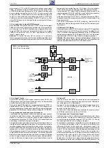
If the feedback voltage decreases by a small amout due to a heavier
load the drive pulse to the transistor T665 is prolonged. As a result, the
conducting period of T665 will be longer so that additional energy
transfer will be provided to compensate for the load. Pin 3 of IC630 is
a current sense input and will stop the drive to T665 at IC630-(6) in the
event of excessive current drain from a heavy secondary load.
If there was a short circuit condition at the transistor T665, the circuit
UC3842 would be destroyed. Therefore, the diodes D666 and D664
are provided to avoid the voltage at pin 3 exceeding 1.2V. The
components D668, C669, and R669 work as a snap stage.
The components CD654, C656, CD656, and CR656 delay the rise of
the pulse start duration (soft start).
The adjustment control R654 is used to set the secondary voltages by
regulating the +A voltage at minimum brightness and contrast.
1.3 Standby Mode
In normal operating mode, a voltage of approx. 10.5V is present on
IC676-(1) (LM317). If the TV receiver is to be switched to standby, the
µ
P switches U
Standby
to "High" level so that the level on IC676-(1) is
< 0.7 V. As a result, the vB is switched off and the TV receiver
goes to standby.
1.4 Secondary Voltages
+A:
Supply for the horizontal output stage from the winding 5/9
and D682. The power supply unit is set to this level.
+33V: The upper tuning voltage limit for the tuner is produced at the
Z-diode D683 and the resistors R681 from the winding 5/9 via
D682.
+M =16.5V Supply for the sound output stage from the winding 7/5 and
the diode D671.
+B = 12V
Power supply for the Tuner, SAT-module and the horizon-
tal driver T501. This voltage is supplied from the winding
7/5 via the diode D671 and is stabilised by the adjustment
control IC676. Switching off of the +12V supply, see
"Standby Operation".
+E = 8V
Power supply for the Video Processor IC150. In Standby
mode it is switched off.
+H = 5V
Power supply for the
µ
P IC850, the infrared amplifier
IR810, the Videotext IC2810, Tuner, and CIC105.
This voltage is also present in Standby mode.
Additionally necessary voltages
+D: 25V
Power supply for the vertical output stage from the line
transformer winding B/H via D444.
+C: 125V
The power supply for the picture tube panel is obtained
190V
from the line transformer winding G/H via R543 and the
diode D543. 130V/14" CRT; 200V/15…21" CRT.


