


M 49-DPL
Allgemeiner T
eil / General Section
GRUNDIG
Service
1 - 7
Important :
Before you begin operating the system, complete
the preparation procedures.
When the mains plug is connected to the wall
socket, the set will enter the STANDBY mode. The
standby indicator
6
lights up and
0
:
00
blinks on
the display.
Switching the system ON
• Press
ON/OFF
y
,
CD
,
TUNER
,
TAPE
or
AUX
on
the set or on the remote control.
Switching the system to standby mode
• Press
ON/OFF
y
again (or
y
on the remote
control).
Selecting the Sound Source
• Press the respective source selection:
CD
,
TUNER
,
TAPE
or
AUX
on the set or the remote
control.
– The name of the selected sound source scrolls
once on the display.
Note :
For AUX source, ensure that you had
connected the audio left and right output terminals
of the external equipment (e.g. TV or VCR) to the
AUX IN sockets.
Demo mode
The system has a demonstration mode that shows
the various features offered by the system.
• Press
DEMO
on the remote control to switch on
the demonstration.
– The display will show “
DEMO ON
” and
“
WELCOME TO THE AUDIO WORLD
” followed
by a demonstration of the various features.
• Press
DEMO
again or
ON/OFF
y
(or
y
on
remote control) to stop the demonstration mode.
– The set enters the standby mode.
OPERATING THE SYSTEM
10
2
9
1
4
11
3
6
5
8
7
1
2
3
CD
10
2
9
1
4
11
3
6
5
8
7
1
2
3
11 5005
➥
VOL 12
Hz
10K
3K
1K
340
105
Sound control
Volume Adjustment
• Rotate
VOLUME
right or left (or press
or
–
on the remote control) to
increase or decrease the sound level.
– The display indicates the selected level.
For Personal Listening
• Connect the headphones to the
p
socket
(3.5 mm) at the front of the set. The
speakers will be muted.
Preset equalizer
The preset equalizer feature creates a realistic
atmosphere for the style of music you select
using the latest digital sound technology.
• To enjoy a special sound effect, press
PRESET EQ
on the set or on the remote
control.
– The display shows the selected effect:
,
, ,
or
NORMAL
.
Ultra Bass System (UBS)
• Press
UBS
to enhance the bass response.
– The
flag lights up.
UBS
CLASSIC
JAZZ
ROCK
DISCO
Dolby Pro Logic
This state of the art Dolby Pro Logic mini system
enables you to experience and enjoy a Home
Cinema sound ambience.
Dolby Pro Logic is a coding system that enables
a set to decode 4 sound channels out of a
normal stereo signal: the center channel for
picture related sounds, both front left and right
channels for stereo sounds and one surround
channel for the rear to bring room and depth to
the scene.
The surround signal is reproduced by two
speakers placed towards the rear of the listening
area. Although the surround signal is mono, a
pair of speakers is necessary to produce the
correct diffused sound field.
Dolby Pro Logic manufactured under license from
Dolby Laboratories Licensing Corporation.
DOLBY, the double-D symbol
d
and ‘PRO
LOGIC’ are trademarks of Dolby Laboratories
Licensing Corporation.
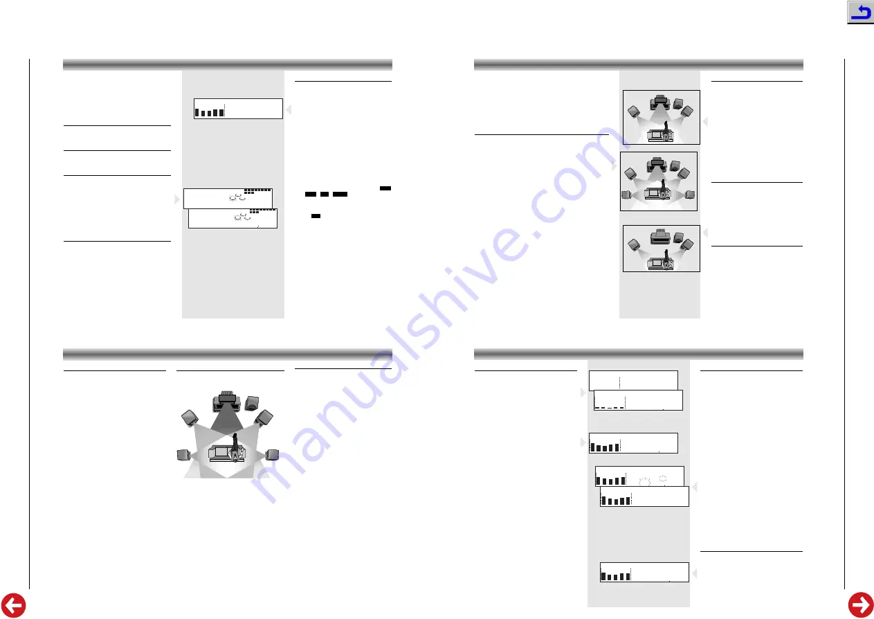
General hints for speaker positioning
Avoid positioning the speakers in a corner or on
the floor, as this will boost the bass tones too
much. Placing the speakers behind curtains,
furniture etc. will reduce the treble response, thus
reducing the stereo effect considerably. The
listener should always be able to ‘see’ the
speakers.
Each room has different acoustic characteristics
and the positioning possibilities are often limited.
You can find the best position for your speakers
by following the picture on the right. The
speakers should always be arranged as
symmetrically as possible in the room.
DOLBY PRO LOGIC
Setting up the Dolby Pro Logic system
A full Pro Logic system needs 5 speakers that should
be connected and positioned as illustrated below.
Positioning the center speaker
The center speaker should be placed in the center
between both front speakers, e.g. underneath or on
top of the TV. The best height for the center speaker
is at the height of the listener’s ears (while seated).
Note: to avoid interference with the TV picture, use
only a magnetically shielded center speaker.
Positioning the surround speakers
The surround speakers connected to the
SURROUND L
terminals of the amplifier should be on the left and
the surround speaker connected to the
SURROUND
R
terminals of the amplifier on the right side of the
listener in the room.
The surround speakers should face each other and
be in line with, or at most 1.5m behind the listener.
LEFT
FRONT
RIGHT
FRONT
TV
CENTRE
SURROUND
LEFT
SURROUND
RIGHT
HIFI MINI
SYSTEM
Test tone
The test tone feature enables you to adjust the
sound level of the Center speaker and
Surround speakers respectively in the Dolby
Pro Logic mode. While the feature is activated
also the balance settings of the left and right
Front speakers are indicated, but cannot be
changed.
We advise you to sit down at the normal
listening position when performing this
operation.
1
Switch on the set, for instance by pressing
one of the source keys on the remote
control:
CD
,
TUNER
,
TAPE
,
AUX
.
2
Press
TEST TONE
on the remote control.
– You will now hear a test tone from the left,
center, right and rear speakers in turn, in a
repeating cycle.
3
During the time that
CNTR
is shown on the
display, you can press
+
or
–
to adjust the
center level setting.
– The display shows e.g.
CNTR +1
or
CNTR
-1
.
4
During the time that
REAR
is shown on the
display, you can press
+
or
–
to adjust the
surround level setting.
– The display shows e.g.
REAR +1
or
REAR
-1
.
5
When perception of all levels is equal,
press
TEST TONE
again to turn off the test
tone.
Note:
The test tone feature does not work
when the set is in Normal Stereo mode.
When you have completed the Dolby Pro Logic setup, you are
ready to experience and enjoy a Home Cinema sound ambience
• Press
DOLBY SURROUND
on the unit or
SURR. MODE
on the
remote control repeatedly to select and cycle through the
three sound modes:
Dolby Pro Logic –> Dolby 3 Stereo –>
Stereo –> Dolby Pro Logic –> etc.
• For the best Dolby Pro Logic sound, it is recommended to
select the setting
CLASSIC
with the
PRESET EQ
button.
Dolby Pro Logic
Choose this setting for playback of music and movies (especially
Laser Discs, videocassettes and TV broadcasts with DOLBY
SURROUND sound). Not only does Dolby Pro Logic surround
you with sound, it also gives you a clear perception of the posi-
tion and direction of the sound. In this mode you use 5 speakers:
front left and right, a center speaker and two surround speakers.
• Press
DOLBY SURROUND
on the unit or
SURR. MODE
on the
remote control to select this setting.
– The display will show ’
PRO LOGIC
’.
• If you press within 4 seconds the
1
or
2
buttons you can
adjust the L/R Front speaker balance.
– The display shows
BAL 0
as default setting.
• Press within 4 seconds the
2
button repeatedly to attenuate the left
channel. The display will show from
BAL R1
up to
BAL R15
.
• Press within 4 seconds the
1
button repeatedly to attenuate the right
channel. The display will show from
BAL L1
up to
BAL L15
.
• Press within 4 seconds
DOLBY SURROUND
on the unit or
SURR. MODE
on the remote control again.
– The display shows
CNTR 0
(default setting).
• If you press within 4 seconds the
1
or
2
buttons you can adjust
the center level (related to the front level from –10 to +10 dB)
– The display shows e.g.
CNTR +06
• Press
DOLBY SURROUND
on the unit or
SURR. MODE
on the
remote control again.
– The display shows
REAR 0
(default setting).
• If you press within 4 seconds the
1
or
2
buttons you can adjust
the rear level (related to the front level from –10 to +10 dB).
– The display shows e.g.
REAR +04
DOLBY PRO LOGIC
Note:
After power failure or disconnecting the
unit from the mains, the speaker levels
will be set to their default values.
LEFT
FRONT
RIGHT
FRONT
TV
HIFI MINI
SYSTEM
LEFT
FRONT
RIGHT
FRONT
TV
CENTRE
HIFI MINI
SYSTEM
SURROUND
LEFT
SURROUND
RIGHT
LEFT
FRONT
RIGHT
FRONT
TV
CENTRE
HIFI MINI
SYSTEM
Dolby 3 Stereo
Choose this setting for playback of music and
movies (especially Laser Discs, videocassettes
and TV broadcasts with DOLBY SURROUND
sound), when not using rear speakers. You
get a clear perception of the position and
direction of the sound.
In this mode you use only front and center
speakers, the rear speakers are not switched
on.
• Press
DOLBY SURROUND
on the unit or
SURR. MODE
on the remote control several
times to select this setting.
– The display will show
3 STEREO
.
• The speaker levels of L/R Front speaker
and Center speaker can be adjusted as
described in Dolby Pro Logic mode.
Normal Stereo Mode
In this case the center and rear speakers are
switched off for normal stereo operation.
• Press
DOLBY SURROUND
on the unit or
SURR. MODE
on the remote control several
times to select this setting.
– The display will show
STEREO
.
• The speaker levels of L/R Front speaker
can be adjusted as described in Dolby
Pro Logic mode.
Center mode
• Use the
CENTER MODE
button on the set
to select the center channel mode:
NORMAL
,
WIDE
or
PHANTOM
.
– Select
NORMAL
if you are using a normal
center speaker.
– Select
WIDE
if you have connected a HiFi
center speaker
– Select
PHANTOM
if you have not connected
a center speaker, but still wish to simulate
the sound coming from the center.
TUNER
Tuning to radio stations
1
Press
TUNER
(
BAND) on the unit or on the
remote control.
– First
TUNER
scrolls once on the display and
after a few seconds it will show the current
frequency or the station name if available.
2
Press
TUNER
again to select the desired
waveband: FM, MW or LW.
3
Press
TUNING
S
or
T
for more than
one second.
– The display will search the frequency until a
station with sufficient signal strength is found.
– The
STEREO TUNED
or
TUNED
flag will light up.
• Repeat this procedure until the desired station
is reached.
• To tune to a weak station, briefly press
TUNING
S
or
T
until the display shows
the right frequency and/or when the best
reception has been obtained.
• When tuning to a station in FM, the unit
always selects FM STEREO. If stereo reception
is disturbed you can press
FM ST
on the remote
control to select FM MONO.
TUNED
PRESET
STEREO
Hz
10 9850M
Hz
10K
3K
1K
340
105
TUNED
PRESET
STEREO
Hz
10 9850M
Hz
10K
3K
1K
340
105
TUNED
PRESET
STEREO
STORED
Hz
10K
3K
1K
340
105
➥
TUNED
STEREO
Hz
Hz
10K
3K
1K
340
105
FM10300M
TUNER
Hz
10K
3K
1K
340
105
FM 8700M
➥
Hz
Hz
10K
3K
1K
340
105
Storing Preset Stations
You can store up to 20 stations in the FM
waveband, 10 stations in the MW and 10
stations in the LW waveband in the memory.
When a preset station is selected, the preset
number appears next to the frequency on the
display.
Manual programming
1
Press
TUNER
(
BAND) on the set or remote
control to select TUNER mode.
2
Press
TUNER
again to select the desired
waveband: FM, MW or LW.
3
Press
TUNING
S
or
T
to tune to the
desired frequency.
4
Press briefly
PROGRAM
– The
PRESET
flag flashes on the display.
5
Press
PRESET
A
or
B
(or
A
or
B
on the
remote control) to select a preset number.
– The preset number flashes on the display.
6
Press
PROGRAM
again.
– The station and the preset number are stored
and
STORED
scrolls on the display.
• Repeat the above procedure to store other
preset stations.
Note:
In case of a power interruption the preset
stations will be kept in the memory for at
least one hour.
Tuning to Preset Stations
• Press
PRESET
A
or
B
(or
A
or
B
on the
remote control) to select the desired preset
number.
– The preset number and frequency appear on
the display.


