


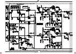
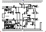


Einstellvorschriften / Adjustment Procedures
CCF 23
2 - 6
GRUNDIG Service
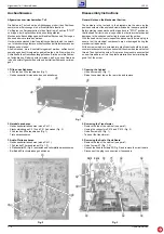
Bandlaufprüfung
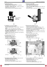
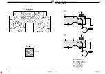
- Laufwerke ausbauen, siehe Pkt. 6 der Ausbauhinweise.
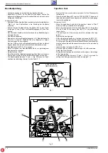
- Kopflehre 401 (Sach. Nr. 72008-401.00) auflegen. Achten Sie
dabei auf die Bandselectoren (Cassettenfühler) und eine korrekte
Auflage der Kopflehre.
Laufwerk A oder B
- Schieben Sie den Kopfschlitten mechanisch in die Gerätefunktion
"Start", d.h. den Kopfschlitten in die Richtung der Kopflehre
schieben.
- Führen Sie den Fühlhebel B der Kopflehre 401 zu den Band-
führungen
4
und
5
, bzw. zur Bandführungsgabel
3
des Ton-
kopfes.
- Der Fühlhebel B muß sich leicht zwischen den Bandführungen
bewegen lassen.
- Kopflehre abnehmen.
- Danach ist mit einer Bandlaufcassette (z. B. Bandlaufcassette
MC-112 C, Sach-Nr. 72008-247.00) der Bandlauf in beiden
Laufrichtungen zu kontrollieren.
Bei der Prüfung mit der Bandlaufcassette muß das Laufwerk
angeschlossen und das Gerät elektrisch betriebsbereit sein.
- Bandlaufcassette MC-112 C einlegen.
- Durch Umspulen der Bandlaufcassette ist ein geräteeigener
Bandwickel zu erzeugen.
- Gerätefunktion: Start.
- Beim Durchlauf der Bandlaufcassette darf das Band nicht an den
oberen oder unteren Kanten der Bandführungen umknicken.
- Die Kopfeinstellschrauben
1
und
2
(Fig. 2) dienen zur Kopf-
spaltsenkrechtstellung (Azimut), siehe Seite 2 - 1.
Tape Run Test
- Remove the drive mechanisms, see para 6 of the Disassembly
Instructions.
- Place the Head Gauge 401 (part no. 72008-401.00). Take care of
tape selectors (cassette sensing levers) and that the head gauge
is correctly positioned.
Drive mech. A or B
- Move the head base by hand to the position it takes in "Start"
mode by sliding it towards the head gauge.
- Move the sensing lever B of the head gauge 401 to the guides
4
and
5
and to the tape guide fork
3
of the soundhead
respectively.
- The sensing lever B must move smoothly between the tape
guides.
- Remove the head gauge.
- With a tape test cassette (eg. the tape test cassette MC-112 C,
part no. 72008-247.00) check the tape transport in both directions.
For carrying out the test with the test cassette the drive mechanism
must be connected and the cassette recorder must be electrically
operable.
- Insert the tape test cassette MC-112 C.
- Wind the tape to produce a specific tape roll of this machine.
- Select the Start function.
- During this test the tape must not bend on the upper or lower edge
of the tape guides.
- The head adjustment screws
1
and
2
(Fig. 2) are used for
setting the head gap angle (azimuth); see page 2 - 4.
Kopflehre
Head gauge
401
SCHIEBER A
SLIDER A
KOPFLEHRE 401
HEAD GAUGE 401
Fig. 1
Fig. 2
Deck B
FÜHLHEBEL B
SENSING LEVER B
5
4
3
2
1
FÜHLHEBEL B
SENSING LEVER B


