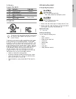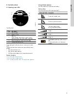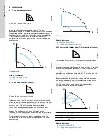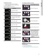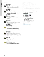
5. Installation requirements
5.1 Optimal installation and operation
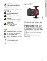
See below for information about the installation and setting of the
product:
•
Slow down the flow to dissipate the heat in the zones
faster. This will also cause a larger temperature difference (delta
T) between inlet and outlet of the boiler that keeps the boiler
from short cycling.
•
By having a larger delta T going back to the boiler, eventually
the boiler starts to condense. The efficiency of the
boiler and system increases, thereby saving money and wear
and tear on your system.
•
In order to to create a flow in a system, the pump needs to
neutralize the system head loss before it can create a flow in the
system.
•
In case there is too little heat at the far end of the installation,
choose a higher setting on the pump or increase the boiler
supply temperature.
•
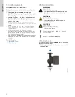
When mounting the pump, the control box must never
be straight up, which is when the shaft is in a vertical position
(air can get trapped inside and damage the pump), or straight
down (bearings will wear out faster).
•
Make sure that you have the proper voltage and are connected
properly (black = phase, white = neutral, green or bare copper
= ground).
Related information
6.1 Mounting the product
7.1 Wiring the pump
6. Mechanical installation
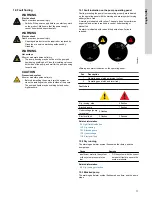
WARNING
Electric shock
Death or serious personal injury
‐
A damaged product must be repaired or replaced by
Grundfos or a service workshop authorized by
Grundfos.
CAUTION
Crushing of feet
Minor or moderate personal injury
‐
Wear safety shoes when opening the box and
handling the product.
CAUTION
Sharp element
Minor or moderate personal injury
‐
Wear protective gloves.
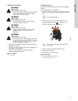
The pump must always be installed with a horizontal
motor shaft within ± 5°.
The pump is a non-submersible pump.
6.1 Mounting the product
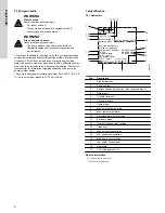
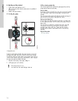
The arrows on the pump housing indicate the flow direction through
the pump. See the figure below.
1. Fit the two gaskets supplied with the pump when you mount the
pump in the pipe.
TM082452
8
English (US)


