11
English (US)
6. Control mode and signals
6.1 Internal control principles
GRUNDFOS UPML and UPMXL AUTO automatically control the
differential pressure by adjusting the pump performance to the
actual heat demand, without the use of external components.
Two different control modes are available:
6.1.1 GRUNDFOS AUTOADAPT
The Grundfos AUTOADAPT function enables the circulator to
control the pump performance automatically within a defined
performance range.
• Adjusting the pump performance to the size of the system.
• Adjusting the pump performance to the variations in load over
time.
Two different control modes are available for Grundfos
AUTOADAPT:
6.2 External control principles
6.2.1 PWM
GRUNDFOS UPML and UPMXL PWM circulators are controlled
via a digital low-voltage pulse-width modulation (PWM) signal
which means that the speed of rotation depends on the input
signal. The speed changes as a function of the input profile.
These communication signals are standardized in the VDMA
Einheitsblatt 24224 “Wet runner circulating pumps - Specification
of PWM control signals”.
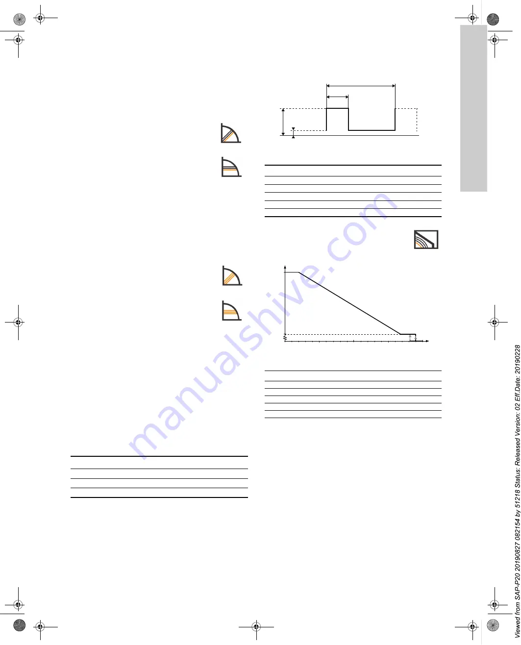
Digital low-voltage PWM signal
The square-wave PWM signal is designed for a 100 to 4000 Hz
frequency range. The PWM signal is used to select the speed
(speed command) and as feedback signal. The PWM frequency
of the feedback signal is fixed at 75 Hz in the pump.
Duty cycle: d % = 100 x t/T
Fig. 11
PWM signal
Fig. 12
PWM input profile A (heating)
PWM feedback signal - Power consumption
PWM feedback signal to system control: power consumption and
various alarms such as under-voltage warning, under-voltage,
stop, locked rotor, internal failure and confirmation of standby
mode.
Proportional Pressure
The differential pressure increases at increased
flow.
Constant Pressure
The differential pressure is constant.
Proportional Pressure AUTOADAPT
In proportional pressure AUTOADAPT, the circulator
is set to proportional-pressure control.
Constant Pressure AUTOADAPT
In constant pressure AUTOADAPT, the circulator is
set to constant-pressure control.
Example
Rating
T = 2 ms (500 Hz)
U
IH
= 4-24 V
t = 0.6 ms
U
IL
≤
1 V
d %= 100 x 0.6 / 2 = 30 %
I
IH
≤
10 mA (depending on U
IH
)
TM
04 99
11
02
11
Abbreviation
Description
T
Period of time [sec.]
d
Duty cycle (t/T)
U
iH
High-level input voltage
U
iL
Low-level input voltage
I
iH
High-level input current
PWM input signal profile A (heating)
At low PWM signal percentages, the circulator
speed is high for safety reasons.
TM0
7 057
9 041
8
PWM input signal [%] Pump status
≤
10
Maximum speed: Max.
> 10 /
≤
84
Variable speed: Min. to max.
> 84 /
≤
91
Minimum speed: Min.
> 91 /
≤
95
Hysteresis area: On/off
> 95 /
≤
100
Standby mode: Off
T
t
U
iH
U
iL
5
10
20
30
40
50
60
70
80
90
100
Max.
Min.
Stop
UPMM_UPML_UPMXL_US.book Page 11 Tuesday, February 26, 2019 10:18 PM
Содержание UPML
Страница 2: ...2 UPMM_UPML_UPMXL_US book Page 2 Tuesday February 26 2019 10 18 PM...
Страница 16: ...16 UPMM_UPML_UPMXL_US book Page 16 Tuesday February 26 2019 10 18 PM...
Страница 17: ...17 UPMM_UPML_UPMXL_US book Page 17 Tuesday February 26 2019 10 18 PM...
Страница 18: ...18 UPMM_UPML_UPMXL_US book Page 18 Tuesday February 26 2019 10 18 PM...


