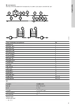
Pos.
Description
X:
External input signal from 0 to 100 %
Y:
Setpoint influence from 0 to 100 %
X1:
Actual input signal, 60 %
Y1:
Sensor maximum [bar]
Y2:
Setpoint [bar]
Y3:
Actual setpoint [bar]
Y4:
Sensor minimum [bar]
Example of a constant curve with linear influence function
Actual setpoint: actual input signal x (setpoint - user-set minimum speed) + user-set minimum speed.
At a user-set minimum speed of 25 %, a setpoint of 85 % and an external setpoint of 60 %, the actual setpoint is 0.60 x (85 - 25) + 25 = 61 %.
100
0
100 %
0
3.5 V
0.5
5 V
0
10 V
0
20 mA
0
20 mA
204 °C
4
-50
25
61
85
Y1
Y2
Y3
Y4
X1
Y
X
TM070253
Pos.
Description
X:
External input signal from 0 to 100 %
Y:
Setpoint influence from 0 to 100 %
X1:
Actual input signal, 60 %
Y1:
Y1: Fixed maximum speed in percentage
Y2:
Y2: Setpoint speed in percentage
Y3:
Y3: Actual setpoint speed in percentage
Y4:
Y4: User-set minimum speed in percentage
6.14.1 “Setpoint influence” functions
6.14.1.1 "Linear function"
The setpoint is influenced linearly from 0 to 100 %.
100 %
0
3.5 V
0.5
5 V
0
10 V
0
20 mA
0
20 mA
4
-50
100
0
204°C
X
Y
TM070255
49
English (GB)
Содержание RADIOMODULE 2G4
Страница 2: ......

