


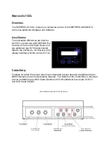


The Controller has the additional circuitry and connector fitted to accept a 2nd Pressure Sensor
for the (HOT) plumbing circuit at connector J8.The existing transducer connector is the
COLD circuit. BOTH transducers need to be connected, otherwise a SYSTEM FAILURE
condition will exist.
Main PCB (Internal Front View)
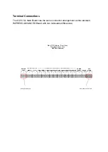
Terminal Connections
IMpress H/C
Note: Greyed-out terminals may not be installed in this version
PUMP-A
RUN
J110
PUMP-B
RUN
J111
PRESS
LOW
J101
PRESS
HIGH
J102
WATER
LOW
J103
WATER
LEAK
J104
PUMP-A
FAULT
J105
PUMP-B
FAULT
J106
SERVCE
DUE
J107
SYSTEM
FAULT
J108
TELEMETRY VOLT-FREE CONTACTS - 250mA/100vDC MAX
COMMS
RS232
RXD GND TXD
J109
WATER
LOW
J5
AUX
ALARM
WH BN BL
J16
REMOTE
NO C NC
J2
STOP
NO C NC
J3
VOLT-FREE CONTACTS
DOSING
PUMP
E L N
J14
AUX Alarm Sensor Input
J6
ZONE-A
COLD
PRESSURE
TRANSDUCER
J8
ZONE-B
HOT
PRESSURE
TRANSDUCER
2nd (HOT) Pressure Transducer Input
Terminal Connections


