background image

8

Original installation and operating instructions.

CONTENTS

Page

1.

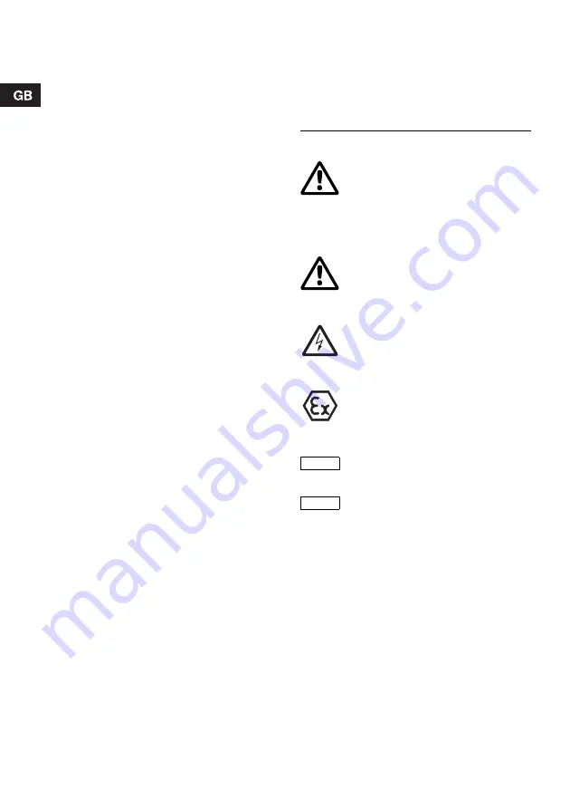
Symbols used in this document

8

2.

General description 

8

2.1

Applications 10

3.

Operating conditions

10

3.1

Installation depth 

10

3.2

Operating pressure

10

3.3

Operation

10

3.4

pH value

10

3.5

Liquid temperature

10

3.6

Density of pumped liquid

10

4.

Approvals

11

4.1

Approval standards

11

4.2

Explanation to Ex approval

11

5.

Identification

12

5.1

Nameplate

12

5.2

Type key

13

6.

Safety

14

7.

Transportation and storage

14

8.

Installation

14

8.1

Installation on auto coupling 

15

8.2

Free-standing submerged installation 

16

9.

Electrical connection

16

9.1

CIU unit (communication interface)

17

9.2

Electrical connection – single-phase 
pumps

17

9.3

Electrical connection – three-phase 
pumps

17

9.4

Alarm relay/communication connection

17

10.

Configuration

18

10.1 Default settings

18

10.2 Pump alternation

18

10.3 Start level set

18

10.4 Thermal switches

19

11.

Start-up 19

11.1 Before start-up

19

11.2 Operating modes

20

11.3 Direction of rotation

20

11.4 Resetting the pump

20

12.

Maintenance and service

20

12.1 Recommended cleaning intervals 

for sensors in standard pumps

21

12.2 Required cleaning intervals for 

sensors in explosion-proof pumps

21

12.3 Inspection intervals

21

12.4 Adjustment of impeller clearance

22

12.5 Cleaning the pump housing

22

12.6 Cleaning the sensors

22

12.7 Checking/replacing the shaft seal

22

12.8 Oil change

23

12.9 Service kits

24

12.10 Built-in protection

25

12.11 Contaminated pumps

25

13.

Fault finding chart

26

13.1 Megging

26

14.

Technical data

27

14.1 Supply voltage

27

14.2 Enclosure class

27

14.3 Ex protection

27

14.4 Insulation class

27

14.5 Pump curves

27

14.6 Sound pressure level

27

15.

Disposal

27

1. Symbols used in this document

2. General description 

The electronic Grundfos DP and EF pumps 
incorporate a controller and motor-protective 
functions. They only need to be connected to the 
mains supply.

The controller offers the following benefits:

Built-in level and dry-running sensors.

Built-in motor protection.

Pump alternation.
If several pumps are installed in the same tank, 
the control logic incorporated in the pump will 
ensure that the load is distributed evenly among 
the pumps over time.

Warning

Prior to installation, read these 
installation and operating instructions. 
Installation and operation must comply 
with local regulations and accepted 
codes of good practice.

Warning

If these safety instructions are not 
observed, it may result in personal 
injury!

Warning

If these instructions are not observed, 
it may lead to electric shock with 
consequent risk of serious personal 
injury or death.

Warning

These instructions must be observed 
for explosion-proof pumps. It is 
advisable also to follow these 
instructions for standard pumps.

Caution

If these safety instructions are not 
observed, it may result in malfunction 
or damage to the equipment!

Note

Notes or instructions that make the job 
easier and ensure safe operation.

Содержание DP 10.50

Страница 1: ...g the shaft seal 22 12 8 Oil change 23 12 9 Service kits 24 12 10 Built in protection 25 12 11 Contaminated pumps 25 13 Fault finding chart 26 13 1 Megging 26 14 Technical data 27 14 1 Supply voltage 27 14 2 Enclosure class 27 14 3 Ex protection 27 14 4 Insulation class 27 14 5 Pump curves 27 14 6 Sound pressure level 27 15 Disposal 27 1 Symbols used in this document 2 General description The elec...

Страница 2: ...t pumps The pumps are designed for free standing installation DP 10 65 26 pumps can be installed on an auto coupling system Fig 1 DP 10 50 pump Fig 2 DP 10 65 pump Fig 3 EF 30 50 pump Explanation to figures 1 2 and 3 Warning Special conditions for safe use of DP and EF explosion proof pumps Bolts used for replacement must be class A2 70 or better according to EN ISO 3506 1 The thermal switch in th...

Страница 3: ...ly S1 See section 11 2 Operating modes The EF pumps are suitable for pumping effluent and other liquids with solids up to 30 mm 3 1 Installation depth Maximum 10 metres below liquid level 3 2 Operating pressure Maximum 6 bar 3 3 Operation Maximum number of starts per hour see WebCAPS on www grundfos com 3 4 pH value Pumps in permanent installations can be used for pumping liquids with a pH value b...

Страница 4: ...d European standard Ex The equipment conforms to the harmonised European standard b Control of ignition sources according to EN 13463 6 2005 c Constructional safety according to EN 13463 5 2003 and EN 13463 1 2009 d Flame proof enclosure according to EN 60079 1 2007 II Suitable for use in explosive atmospheres not mines B Classification of gases according to EN 60079 0 2006 Annex A Gas group B inc...

Страница 5: ...ade in Hungary 96770195 2 3 4 5 6 7 8 9 10 11 12 13 14 15 17 18 19 20 21 22 23 24 25 1 16 26 Pos Description Pos Description Pos Description 1 Version 10 Number of phases 19 Maximum liquid temperature 2 Type designation 11 Rated input power 20 Output power 3 Product number 12 Rated speed 21 Power factor 4 Ex mark 13 Rated voltage 22 Rated current 5 ATEX certificate 14 Weight without cable 23 Opera...

Страница 6: ...wastewater pumps Ex The pump is designed according to the ATEX standard stated or Australian standard AS 2430 1 Number of poles 2 poles n 3000 min 1 50 Hz Number of phases 1 Single phase motor Blank Three phase motor Mains frequency 5 50 Hz Voltage and starting method 02 230 V direct on line starting 0B 400 415 V direct on line starting Generation Blank 1st generation A 2nd generation B 3rd genera...

Страница 7: ...hamber See section 12 Maintenance and service The pumps are suitable for different installation types which are described in sections 8 1 and 8 2 The pump housings have an Rp 2 discharge port or a DN 65 PN 10 flange Warning The use of this product requires experience with and knowledge of the product Persons with reduced physical sensory or mental capabilities must not use this product unless they...

Страница 8: ...automatically connect tightly 8 Hang up the end of the chain on a suitable hook at the top of the tank and in such a way that the chain cannot come into contact with the pump housing 9 Adjust the length of the motor cable by coiling it up on a relief fitting to ensure that the cable is not damaged during operation Fasten the relief fitting to a suitable hook at the top of the tank Make sure that t...

Страница 9: ...p is hanging from the chain and not the cable 3 Hang up the end of the chain on a suitable hook at the top of the tank and in such a way that the chain cannot come into contact with the pump housing 4 Adjust the length of the motor cable by coiling it up on a relief fitting to ensure that the cable is not damaged during operation Fasten the relief fitting to a suitable hook Make sure that the cabl...

Страница 10: ...e can be determined with a phase sequence detector The pump does not start unless the phase sequence is correct If the dry running sensors are covered by liquid and the pump does not start the cause may be a wrong phase sequence Interchange L1 and L2 Fig 6 Wiring diagram for three phase pumps 9 4 Alarm relay communication connection The pump incorporates an alarm relay output NC and NO are availab...

Страница 11: ...vel See examples below Example 1 Constant barometric pressure The pump will start when the liquid level in the tank has reached the set start level Then the pump will run until the liquid level reaches the stop level When it stops the pump will calibrate itself in relation to the actual barometric pressure See fig 8 Fig 8 Example 1 Constant barometric pressure Example 2 Rising barometric pressure ...

Страница 12: ... pump incorporates dry running protection based on two dry running sensors placed on either side of the unit If a dry running sensor detects water shortage the pump will stop immediately and cannot restart until the sensors are fully submerged again The sensors must be cleaned at regular intervals depending on the deposits of sludge on the sensors in the tank Note When a thermal switch is activate...

Страница 13: ...s not start with a wrong phase sequence and consequently wrong direction of rotation If the pump does not run and the liquid level is above the dry running sensors interchange L1 and L2 Fig 14 Jerk direction 11 4 Resetting the pump To reset the pump switch off the power supply to the pump for 1 minute and switch it on again 12 Maintenance and service Before carrying out maintenance and service it ...

Страница 14: ...ection 12 9 Service kits Ball bearings Check the shaft for noisy or heavy operation turn the shaft by hand Replace defective ball bearings A general overhaul of the pump is usually required in case of defective ball bearings or poor motor function This work must be carried out by Grundfos or an authorised service workshop Warning When slackening the screws of the oil chamber note that pressure may...

Страница 15: ... the motor part 3 Clean the pump housing and the impeller Assembly 1 Place the motor part with impeller in the pump housing 2 Fit and tighten the clamp See also section 12 7 Checking replacing the shaft seal 12 6 Cleaning the sensors Fig 16 Position of level and dry running sensors Proceed as follows See fig 16 1 Level sensor pos 7 Flush the sensor with clean water Dry running sensors pos 10 Flush...

Страница 16: ...ng hours or at least once a year change the oil in the oil chamber as described below If the shaft seal has been changed the oil must be changed as well See section 12 7 Checking replacing the shaft seal Draining of oil 1 Slacken and remove both oil screws to allow all the oil to drain from the chamber 2 Check the oil for water and impurities If the shaft seal has been removed the oil will give a ...

Страница 17: ...5 96115103 DP 10 50 09 96115104 DP 10 50 15 96115105 DP 10 65 26 96115106 Oil 1 litre of oil type Shell Ondina 917 See section 12 Maintenance and service for required quantity in oil chamber All types 96076171 Lifting bracket Lifting bracket and screw 0 6 1 5 kW 96984147 2 6 kW 96984148 Power plug Plug for power supply and O rings for cover All types 96984144 Protective cap for level sensor Protec...

Страница 18: ...ut the pumped liquid etc before the pump is returned for service Otherwise Grundfos can refuse to accept the pump for service Possible costs of returning the pump are paid by the customer However any application for service no matter to whom it may be made must include details about the pumped liquid if the pump has been used for liquids which are injurious to health or toxic Before a pump is retu...

Страница 19: ...installation and the submersible drop cable d Supply failure short circuit fault in cable or motor winding Have the cable and motor checked and repaired by a qualified electrician e Fault in motor electronics Have the motor checked and repaired by a Grundfos service engineer f Deposits on level or dry running sensors Clean the sensor s 2 The pump operates but the motor stops after a short while a ...

Страница 20: ...m The curves are to be considered as a guide They must not be used as guarantee curves Test curves for the supplied pump are available on request 14 6 Sound pressure level The sound pressure level of the pumps is lower than the limiting values stated in the EC Council Directive 98 37 EC relating to machinery 15 Disposal This product or parts of it must be disposed of in an environmentally sound wa...

Отзывы: