GRUNDFOS
INSTRUCTIONS
www.grundfos.co.uk
Page 21 of 35
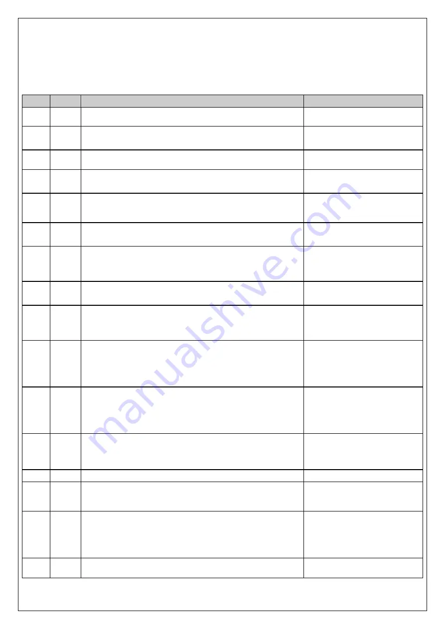
9.5 Commissioning checklist
Before the commissioning phase starts ensure that the
Installation checklist
has been
completed and check the state of the mains power and water supplied to the unit.
Step
Done
Activity
Action/Check/Notes
1
Fully read and study this manual.
2
Ensure that the installation location meets all of the
requirements in this manual and BS 9251 latest revision.
3
Check mains power and water to the unit are both OFF
Ensure both are OFF and cannot be
accidentally turned ON.
4
If necessary, remove the two screws retaining front
cover. Remove front cover. Place to one side.
Do not disconnect earth wire
5
Inspect the Installation, check everything in the
Installation
checklist has been completed.
Check supply tank is full and the
correct capacity. Refer to BS 9251:
2014 Calculation.
6
Make first setting of the pressure switch values according
to the design calculations for the system. Coarse settings.
May require further adjustment
against the pressure gauge later
7
Close the system isolating valve on the discharge side of
unit. Open the system isolating valve on the suction side
of the unit. Apply water to the unit.
8
Prime the CM pump and the whole system as necessary.
Open the discharge isolating valve. Inspect for leaks
Refer to CM pump I&O manual for
guidance. Fix any leaks.
9
Remove the controller cover and fit the 2 x AAA battery’s.
Refit the controller cover and review all of the above
actions. Apply the mains power.
10
Pump will start, run for 20 seconds and pressurise the
system. If necessary, prime/vent the system again.
Check the pressure gauge value is as expected. Inspect
for any leaks
Fix any leaks
11
Tune the pressure switch settings for the system against
the gauge readings and the designed pressures settings
by draining off water and allowing the unit to respond
observing values on gauge.
Ignore any Service/Fault LED’s at
this time.
12
Check the digital inputs give the expected outputs
Tank low water level, Y / N
(Ring answer)
Flow switch, Y / N
(Ring answer)
Optimise retard on flow switch to
prevent false alarms
13
Replace front cover and re-fit the two screws
14
Set the pump test time
Press and hold the Test/Reset
button on the control panel.
Weekly Test time set at this time.
15
Clean up area and ensure safe for user,
Mains isolator is locked in the ON position
Isolating valves locked in the OPEN position
Put system into Service mode and clear any faults
Refer to section 7.1 – Service Mode
16
System is ready for verification
Update the history log at back of
this manual


