5
MAINTENANCE & REPAIR (Refer to Parts Drawing)
Service Precautions
•
Before performing any service operation, always shut off the air supply and release the pressure of the medium, i.e. let the grease out so
that the pressure decreases. When storing the pump assembly without the bucket, cover the Filter Tube (57) with Filter Cap (62).
•
Be careful not to damage any parts when dismantling. While removing shafts which do not have key flats, wrap a thick piece of cloth
around the shaft before removing it with a Pipe wrench, Polygrip wrench or the like. The easiest way to remove such a shaft is to grip it in
a vice with aluminium or copper jaws, clamp the shaft in a hand-drill chuck and then turn the chuck by hand.
•
Be careful when fitting O-rings and seals. Always lubricate them with oil or grease before fitting. They must never be threaded over sharp
edges when being fitted. Lubricate all moving parts with oil or grease.
•
When troubleshooting, be on a lookout for dirt in valves / ball seats, scratches in sealing surfaces & damaged O-rings / seals / gaskets.
•
Pump Cylinder (51) has a pin-hole end that must face
upwards; towards Extension Rod (46).
•
Slide Bush (53) has a slotted end that must always
face upwards; towards Top Coupler (52).
•
When fitting Plunger Rod (9), Connecting Rod (43) &
Plunger Nut (7), apply locking fluid on the threads.
•
Replace Component No. 51, 52, 53 & 55 as a SET.
Drive Section Disassembly & Reassembly
Pumping Section Disassembly & Reassembly
1. Hold the complete pump assembly in a vice & unscrew the
Filter Tube (57). Prevent the Piston Rod (55) from rotating by
inserting a rod through the side hole in Piston Rod. Remove
the Nyloc Nut (61) & Piston Washer (60).
2. Unscrew the Bottom Coupler (54) & remove Slide Bush (53).
Unscrew the Top Coupler (52) & remove lower Steel Ball (47),
Non Return Spring (48), Valve (49) & both O Rings (50).
3. Unscrew the Barrel (63). Drive out the lower Slotted Spring
Pin (44) taking care not to bend the Extension Rod (46).
4. Unscrew the Pump Cylinder (51) from Extension Rod (46).
Remove upper Steel Ball (47) & Non Return Spring (48).
5. Drive out the upper two Slotted Spring Pins (44), unscrew the
Extension Rod (46) and then Connector (45).
6. Assemble by following the steps 1-5 in reverse order taking
care of the points below:
1. Remove Bend Pipe (1) by opening both the Coupling Nuts (2).
Remove both Sealing Rings (3) & unscrew both Bends (4).
Unscrew the Cylinder Cover (5) and Cylinder (10).
2. Unscrew Inlet Cover (32) & dismantle the two Pushers (15)
with their Pusher Springs (17), Pusher Nuts (18) & Pusher
Buttons (19).
3. Remove Circlip (20), both Filters (21), O Ring (22) & Exhaust
Valve (23).
4. Unscrew the Plunger Nut (7) and remove Rubber Plunger (8).
5. Unscrew Plunger Rod (9) from Connecting Rod (43) and
remove Slider (30). Remove Slider Guide (38), its outer O Ring
(37), Seals (39), Seal Support (40) & its inside O Ring (11).
6. Open the two Screws (29) & remove Clip (28), Nylon Slider
(27), Slider Guide (26), Seat (25) & Paper Seal (24).
7. For reassembly of Air Motor, follow the above-mentioned
steps 1-6 in reverse order taking care of the points below:
•
When fitting Pushers (15), open Inlet Cover (32) &
ensure correct installation of Pusher Buttons (19).
•
Conical side of Seals (39) must face upwards.
Assemble Slider guide (38), its outer O Ring (37),
Seals (39), Seal Support (40) & its inside O Ring (11).
Hold them as a set & mount on Connecting Rod (43).
1. Partially open the on/off air valve ( It helps in creating initial vacuum when filling a totally dry pump ). Pump will start operating
automatically until it gets primed. Pump is said to be
Primed
when grease is available at the pump outlet, making the pump ready to use.
Once primed, the air motor will stop. Open the on/off air valve fully.
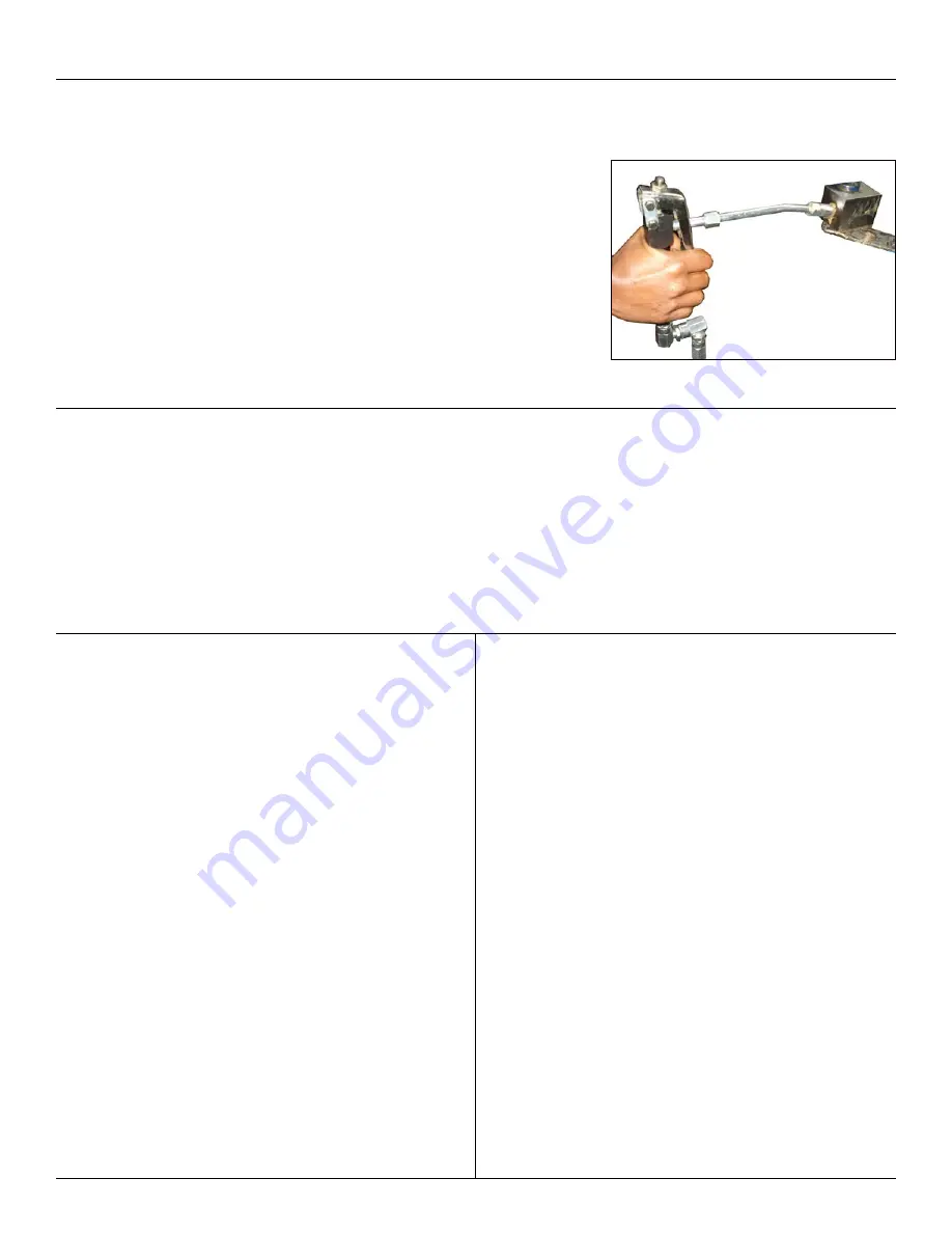
2. Hold the grease control valve near a container & press the trigger. Pump will start
operating with continuous grease discharge as long as the trigger is pressed. Release
the trigger & this will stop the pump. Check for any leaks from any of the connections &
Tighten again if required.
3. Connect coupler fitted onto the control valve extension with the grease nipple & press
trigger. Be careful not to over-lubricate as the pump will keep dispensing grease as long
as the trigger is pressed. Once the trigger is released, pump will stop dispensing grease
& the air motor will stop.
4. When not in use & at the end of each day, air supply to the pump must be switched off.
PUMP OPERATION


