background image

4

3

1.Please  be  clear  which  kind  of  battery  system  you  want,  lithium  battery  system  or 
lead-acid battery system, if you choose the wrong system, SPH can't work normally.

2.Please read this manual carefully before the installation, the company has the right 
not  to  quality  assurance,  if  not  according  to  the  instructions  of  this  manual  for 
installation and cause equipment damage.

3.All  the  operation  and  connection  please  professional  electrical  or  mechanical 
engineer.

4.During installation, please don’t touch the other parts within the box

.

5.All the electrical installation must comply with the local electrical safety standards

.

6.If  equipments  needs  to  maintain,  please  contact  with  local  specify  system 
installation and maintenance personnel

.

7.Use  the  equipment  to  combined  to  grid  needs  to  obtain  the  permission  of  local 
power supply department

.

8.When install PV modules in the daytime,  please turn off the PV switch, otherwise it 
will be dangerous as high terminal voltage of modules in the sunshine.

1.4 Safety Instructions

Safety


2.1 Purpose Use

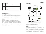
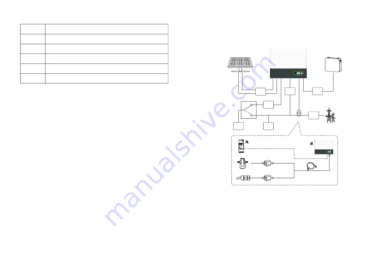
As shown above, a complete grid-connected system of SPH consists of PV modules, 
SPH inverter, battery, utility grid and other components. 

Chart 2.1

Attention:

As  the  system  refer  to  battery  use,  we  must  make  sure  ventilation  of  the  service 
environment  and  temperature  control  in  order  to  prevent  the  danger  of  battery 
explosion,  battery  recommended  installation  environment  must  be  strictly  in 
accordance  with  the  specification,  if  the  specification  is  IP20  environment,  the 
pollution degree of the unit is PD2, meanwhile the temperature should be control in 
the 0-40

 of indoor ventilation and the humidity should be 5%-85%.  If the chosen 

PV  modules  needs  to  positive  or  negative  ground  connection,  please  contact  with 
Growatt for technical support before installation.

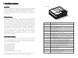
The system chart of SPH:

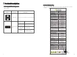
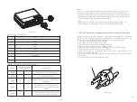
Position

Description

Q

RSD(do not open except by Professional staff)

R

UPS output 

S

Ground point

T

PV input

U

PV switch

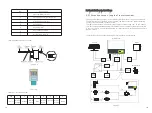
Battery installation requirement

Electic meter

CT

L line

L,N

L,N

10m

5m

5m

30m

AC
Breaker


Breaker

DC
Breaker

Hybrid Inverter

DC
Breaker

AC
Breaker


Sensor

Load

Load

UPS

PV Array

Battery

UPS

Grid

Electrical Grid

1

2

3

TSSP(Optional)

RailLog

Содержание SPH TL BL-UP Series

Страница 1: ... 28 Guangming Road Shiyan Street Bao an District Shenzhen P R China No 28 Guangming Road Shiyan Street Bao an District Shenzhen P R China GR UM 180 A 00 GR UM 180 A 00 86 0755 2951 5888 86 0755 2951 5888 www ginverter com www ginverter com T E W service ginverter com service ginverter com Download Manual Growatt New Energy ...

Страница 2: ... 1 4 Safety Instructions Safety 2 1 Purpose Use 2 2 Safety Measure 2 3 Symbols introduction on the SPH inverter Product Description 3 1 Growatt SPH series inverter 3 2 Label Explanation 3 3 Size and weight 3 4 The advantage of the unit of Growatt SPH Unpacking list 1 2 3 4 ...

Страница 3: ...and shut down SPH system 7 7 1 Start up the SPH system 7 2 Disconnect the SPH system Attention of the installation environment maintenance and cleaning 8 Fault removal 9 12 1 Dismantling the energy storage 12 2 Packing the SPH inverter 12 3 Storing SPH inverter 12 4 Disposing of the SPH inverter Decommissioning EU Declaration of Conformity Manufacturer Warranty 12 10 11 Product specification 13 13...

Страница 4: ...tt SPHTL BL UP Series rapidly and troubleshooting build communication system through read this manual carefully If you have any questions in the process of installation you can login in and leave some message Or you can call our 24 hour service hotline 86 0755 29515888 www growatt com Growatt SPHTL BL UP Series is used to store energy generated by the photovoltaic cell panels or energy from grid i...

Страница 5: ...nshine 1 4 Safety Instructions Safety 2 2 1 Purpose Use As shown above a complete grid connected system of SPH consists of PV modules SPH inverter battery utility grid and other components Chart 2 1 Attention As the system refer to battery use we must make sure ventilation of the service environment and temperature control in order to prevent the danger of battery explosion battery recommended ins...

Страница 6: ...ng instructions Relevant operation for professional personnel Please notice children disabled laypeople do not close Supervise and make sure children don t play near the installation position of energy storage machine Risk of high voltage SPH inverter exists radiation maybe affect health Don t stay a long time within 20cm from SPH inverter PV modules Capacitive Discharge Currents PV modules with l...

Страница 7: ...ample SPH 6000TL BL UP shows as below Mark Description Explanation Push button Status symbol of SPH Operation of display screen and set system Green light on SPH run normally Red light on Fault state Red light blinking Green light blinking 2 Software updating 1 bypass state Alarm state Z_souce 1 05 j 0 32 ohm Maximum short circuit 27 a c A ...

Страница 8: ...ries as follows SPH inverter User Manual Paper board installation guide Waterproof cover AC Grid connector Austrialian machine terminal is different UPS output connector Communication cable Current sensor Lead acid battery temperature sensor RJ45 connector M6 setscrew Battery power terminal Screw MC4 connector A B C D E F G H I J K M N O P Item Number Description Chart 4 1 Q 1 Hex screwdriver 1 1 ...

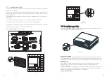
Страница 9: ...nclosed Please refer to the below Chart 5 1 Chart 5 4 Chart 5 3 5 2 Installation requires tools and RJ 45 terminal sequence of the LAN line H Installation position shall not prevent access to the disconnection means I In order to ensure machine can run normally and easy to operate please pay attention to provide adequate space for SPH please refer to below J Do not install the machine near televis...

Страница 10: ...att SPH One is wired current sensor one is meter sensor or RailLog if you choose wired sensor or meter Before installing you should know something that as below The cable of wired sensor and meter is suggested not longer than 15m So you need to consider the length between SPH with combiner box for the sensor should be installed in the live line And if you installed RailLog for sensor distance reco...

Страница 11: ...he whole installation has finished b c 5 4 Grounding connection d Chart 5 8 SPH must be grounded by cable the grounding point is showed as follow and the minimum grounding cable wire is AWG10 PV Array Grounding Grounding conductor of PV panel brackets must be firmly connected to earth at PV array side and inverter side and SP side The sectional area of grounding conductor should be equal to the se...

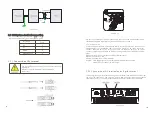
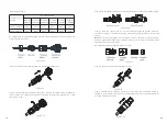
Страница 12: ...f connection cable to positive pole of PV input connector connect negative pole of connection cable to negative pole of PV input connector please pay attention to PV input voltage and current within permission Limit Max PV voltage 550V consider the lowest temperature Max PV input current 12A Max PV input power per string 4000W Remark 1 We suggest you use the cable 4mm2 12 AWG to connect 2 Please d...

Страница 13: ...he Australian machine Chart 5 15 19 20 AC output terminal connection steps as follow Step 2 Thread cables through pressure screw seal ring threaded sleeve in sequence insert cables into connection terminal according to polarities indicates on it and tighten the screws chart 5 18 chart 5 19 chart 5 17 Note The following diagram shows the AC output terminal of the Australian machine connection steps...

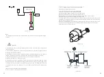
Страница 14: ...mmended wiring diagram is as follows Chart 5 22 SPHInverter ACGRID L L UPS OUTPUT N N E E Sensor L L N N E E TSSP Battery L N PE PV UPS 21 Chart 5 23 Chart 5 24 Note This diagram is an example for gird system without special requirement on electrical wiring connection Note This diagram is an example for Australian and New Zealand gird system where neutral line can t be switched SPHInverter ACGRID ...

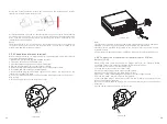
Страница 15: ...S load should be less than 3680W 8 The first start of system needs Grid power SPHInverter L UPS OUTPUT N E L N E Battery PV UPS Note This diagram is an example for customer who only wants to use the off grid storage system Chart 5 25 23 24 Install battery steps are as follows 1 Unscrew the swivel nut from the cable gland 2 Thread the swivel nut over the battery cable 3 Press the cable support slee...

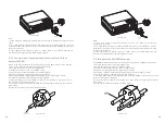
Страница 16: ...rt the RJ45 plug of the network cable into the CT pin connector on the inverter until it snaps into place 8 If no other cables need to be installed lock the waterproof cover to the inverter with screws 9 Screw the swivel nut onto the waterproof cover Chart 5 29 25 Chart 5 30 Chart 5 31 Note 1 Meter and CT can t be installed at same time please set the sensor model when selecting CT or electricity ...

Страница 17: ...tor on the inverter until it snaps into place Chart 5 34 8 If no other cables need to be installed lock the waterproof cover to the inverter with screws 9 Screw the swivel nut onto the waterproof cover Chart 5 33 27 28 Chart 5 35 Note 1 Meter and CT can t be installed at same time please set the sensor model when selecting CT or electricity meter please refer to section 6 3 3 for details 2 Meter m...

Страница 18: ... 8 If no other cables need to be installed lock the waterproof cover to the inverter with screws 9 Screw the swivel nut onto the waterproof cover 29 30 Chart 5 39 Note 1 If you are using a lead acid battery you do not need to install this communication cable 2 The CAN battery communication and 485 2 battery communication can t be installed at same time please select the correct communication metho...

Страница 19: ...tion manual and the signal should be a simple binary output that captured by RJ45 terminal PIN 5 and 1 for detecting the signal Once the signal actived the inverter will reduce its active power to zero within 5s 5 5 9 Connection of temperature probe for lead acid battery When customer using lead acid battery the temperature probe of the lead acid battery is used to detect the ambient temperature o...

Страница 20: ... 3 Press the cable support sleeve out of the cable gland 4 Remove the filler plug from the cable support sleeve 5 Route the network cable through an opening in the cable support sleeve 6 Thread the network cable through the cable gland 7 Thread cables into connection terminal of the inverter then press the terminal by relevant tools and make sure cables are firmly 8 If no other cables need to be i...

Страница 21: ... power rate which less than the battery maximum output power If the customer don t enable the AC CHG AC grid charging function Inverter will charge battery by PV The SPH inverter will be set to the appropriate model according to the standards of different countries or regions before leaving the factory For example the inverter shipped to Australia are configured as Australian model in the factory ...

Страница 22: ...ust turn off PV switch AC breaker and Battery to make sure all of the power are off Caution 1 After setting the DIP please power on the inverter and check the model display show as 6 3 1 If the model display is match what you want it means your setting is successful 2 You need to calibrate the time that the machine is showing after inverter starts up If the country is set incorrectly please shut d...

Страница 23: ...N D I P 6 5 4 3 2 1 ON DIP 6 5 4 3 2 1 ON DIP 6 5 4 3 2 1 ON DIP 6 5 4 3 2 1 ON DIP AS4777 Australia CEI 0 21 G99 GT0XXXXXX3 GT0XXXXXX4 GT0XXXXXX5 VDE AR N 4105 G98 En50549 GT0XXXXXX7 GT0XXXXXX8 GT0XXXXXX9 Poland GT0XXXXXXB GT0XXXXXXC Hungary VDE 0126 GT0XXXXXX1 Thailand MEA GT0XXXXXXE Thailand PEA T0XXXXXXFG EN50438 Ireland GT1XXXXXX3 GT1XXXXXX7 GT1XXXXXX8 GT1XXXXXX9 GT1XXXXXXC France South Afric...

Страница 24: ...represents 20 6 4 2 LED and button instruction Chart 6 3 Location Description Status ESC button cancel control Down button Enter button UP button A B C D E Notice LED showing status of SPH it has two color one is green and another is red Please turn to 3 1 and read the detail of LED 6 4 3 LCD display column LCD display column is used to show the current state basic information and fault informatio...

Страница 25: ... 1 seconds to make sure Press down key to the next item Press enter key more than 1 seconds to make sure Range from 55 to 60V and the accuracy is 0 1V Range from 0 to 75A and the accuracy is 0 1A WorkMode Lead acid LV WorkMode 48V Range from 42 to 50V and the accuracy is 0 1V Basic Parameter Only display when battery type is lead acid Only display when battery type is lead acid Only display when b...

Страница 26: ...Mode Time WorkMode Power Rate 100 Power Rate 100 Priority WorkMode WorkMode Opt Load First default Bat First Grid First WorkMode WorkMode WorkMode AC CHG Enable Disable WorkMode SC _ _ _ _ WorkMode 00 00 00 00 WorkMode Save OK NO WorkMode Time WorkMode 00 00 00 00 WorkMode Save OK NO If battery first is choosen WorkMode Bat First OK NO If you need to enable AC charging function you need key passwo...

Страница 27: ...phone provided by the company Through RS232 interface connect to Wi Fi S shinelink GPRS use computer terminal or mobile phone for data monitoring Chart 6 17 Before use WIFI communication you should make sure the follow PIN1 and PIN2 are ON 6 5 Communication 6 5 1 Use of USB A port USB A port is mainly for firmware updage Through USB connection we can quickly update the software of machine You can ...

Страница 28: ... Disconnect charging source prior to connecting or disconnecting battery terminals f Determine if battery is inadvertently grounded If inadvertently grounded remove source from ground Contact with any part of a grounded battery can result in electrical shock The likelihood of such shock can be reduced if such grounds are removed during installation and maintenance applicable to equipment and remot...

Страница 29: ...the PV terminal please contact Growatt service center if restart can t solve the problem Battery temperature out of specified range for charge or discharge Grid voltage fault Please refer to the local grid standard for more details of the grid frequency Check the AC voltage is in the range of standard voltage in specification Check the grid connection is good or not Check the environment temperatu...

Страница 30: ...estart can t solve the problem Error 411 Internal communication failed Restart inverter Please contact Growatt service center if restart can t solve the problem Read DSP and COM firmware version from LCD or shinebus Check if the firmware is correct DSP and COM firmware version unmatch system fault Error 418 Error 303 Inverter L N reversed or ground failed Check the L line and N line is reversed or...

Страница 31: ...ation of any kind whatsoever with respect to any machine which has been subjected to Misuse abuse neglect or accident Alteration improper installation or application Unauthorized modification or attempted repairs Insufficient ventilation of the product Transport damage Breaking of the original manufacturers seal Non observance of Growatt installation and maintenance instruction Failure to observe ...

Страница 32: ...owatt SPH series energy storage machine product specification Rated AC output power Model Specifications Input data DC Max recommended PV power for module STC Max DC voltage Start voltage Normal voltage MPP work voltage range Max input current of tracker A tracker B Max short current Output AC 3300W 3300W 3300W 3300W 3300W 3300W 4000W 4000W 4000W 4000W 4000W 4000W 550V 150V 550V 150V 550V 150V 550...

Страница 33: ... H D in mm Weight Noise emission typical Altitude Self Consumption Inverter Topology DC DC topology Cooling concept Environmental Protection Rating Relative humidity DC connection AC connection Features Operating temperature range BAT reverse protection yes yes yes yes yes yes 450 565 180 27KG 25 C 60 Cwith derating above 45 C 25 C 60 Cwith derating above 45 C 25 C 60 Cwith derating above 45 C 25 ...

Страница 34: ...d for data record Used for data record Used for data record RS485 meter sensor CHNT Rs485 meter sensor Estron RS485 meter sensor standard using for on grid and off gird switch manual MR00 0007200 MR00 0008600 MR00 0009601 MR00 0008800 MR00 0008300 TV03 0001200 MR00 0010800 MR00 0008400 Grid regulation EMC Safety NRS 097 2 1 NRS 097 2 1 NRS 097 2 1 EN61000 6 1 EN61000 6 3 EN61000 6 1 EN61000 6 3 EN...

Страница 35: ...t 264 5 V 200ms 59 S2 Limit 264 7 V 180ms 59 S2 Pass 230 8 V xxx V 59 S2 Testing 195 5 V 400ms 27 S1 Limit 194 7 V 380ms 59 S2 Pass 50 01 xxxxHz 81 S2 Testing 51 5HZ 100ms 81 S2 Limit 51 52HZ 80ms 81 S2 Pass 50 01 xxxxHz 81 S2 Testing 47 50HZ 100ms 81 S2 Limit 47 49HZ 80ms 81 S2 Pass 230 4 xxxxV 59 S1 Testing 253 0V 3000ms 59 S1 Limit 254 7V 3000ms 59 S1 Pass 230 4 xxxxV 27 S2 Testing 92 0V 200ms ...

Отзывы: