background image


14 

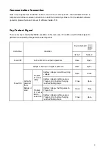
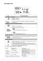
LCD Display Icons 


Icon 

Function Description 

Input Source Information 


Indicates the AC input. 


Indicates the PV input 


Indicate input voltage, input frequency, PV voltage, battery voltage and 
charger current. 

Configuration Program and Fault Information 


Indicates the setting programs. 


Indicates the warning and fault codes. 

Warning:


flashing with warning code.


Fault:lighting with fault code 

Output Information 


Indicate output voltage, output frequency, load percent, load in VA, load in 
Watt and discharging current. 

Battery Information 


Indicates battery level by 0-24%, 25-49%, 50-74% and 75-100% in battery 
mode and charging status in line mode. 


These two signs indicate the charge priority. SOLAR indicates solar first. 

UTILITY indicate utility first. SOLAR blinking indicates solar only; SOLAR and 
UTILITY both on indicates combined charging.


In AC mode, it will present battery charging status. 

Status 

Battery voltage 

LCD Display 


Constant 
Current mode / 
Constant 
Voltage mode 

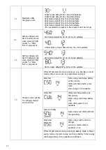
<2V/cell 

4 bars will flash in turns. 

2 ~ 2.083V/cell 

Bottom bar will be on and the other three 
bars will flash in turns. 

2.083 ~ 2.167V/cell 

Bottom two bars will be on and the other 
two bars will flash in turns. 

> 2.167 V/cell 

Bottom three bars will be on and the top 
bar will flash. 

Floating mode. Batteries are fully charged. 

4 bars will be on. 


Содержание SPF 10000T DVM-MPV

Страница 1: ...Off Grid MPV Solar Inverter Split Phase 4KW 12KW Version 1 0 User Manual...

Страница 2: ...Inspection 4 Preparation 4 Battery Connection 5 AC Input Output Connection 8 PV Connection 10 Communication Connection 11 Dry Contact Signal 11 Operation 13 Power ON OFF 13 Operation and Display Pane...

Страница 3: ...k of injury charge only deep cycle lead acid type rechargeable batteries Other types of batteries may burst causing personal injury and damage 4 NEVER cause AC output and DC input short circuit Don t...

Страница 4: ...onsult with your system integrator for other possible system architectures depending on your requirements The WiFi GPRS module is a plug and play monitoring device to be installed on the inverter With...

Страница 5: ...tatus indicator 4 Charging indicator 5 Fault indicator 6 Function buttons 7 Battery 8 Battery 9 Fan 10 Remote control port 11 Dry contact 12 USB port 13 WiFi GPRS device port 14 BMS optional 15 RS485...

Страница 6: ...ng where to install Do not mount the inverter on flammable construction materials Mount on a solid surface Install this inverter at eye level in order to allow the LCD display to be read at all times...

Страница 7: ...lement battery connection 1 Assemble battery ring terminal based on recommended battery cable and terminal size 2 Connect all battery packs as units requires It s suggested to connect at least 200Ah c...

Страница 8: ...f battery to BMS communication port of inverter 4 The other end of RJ45 insert to battery comm port Note if choosing lithium battery make sure to connect the BMS communication cable between the batter...

Страница 9: ...ium Only suitable when communicate with BMS The lithium battery BMS communication protocol options When the battery type set to Li the setting option 12 13 21 will change to display percent Note When...

Страница 10: ...cable for AC input connection To reduce risk of injury please use the proper recommended cable size as below Suggested cable requirement for AC wires Model Gauge Torque Value 4KW 5KW 10 AWG 1 4 1 6 Nm...

Страница 11: ...as inside of circuits If a power shortage occurs and recovers in a short time it will cause damage to your connected appliances To prevent this kind of damage please check with manufacturer of air con...

Страница 12: ...Voc of PV modules not exceeds max PV array open circuit voltage of inverter 2 Open circuit Voltage Voc of PV modules should be higher than min battery voltage Solar Charging Mode INVERTER MODEL 4KW 5...

Страница 13: ...when battery voltage reaches warning level Unit Status Condition Dry contact port NC C NO C Power Off Unit is off and no output is powered Close Open Power On Output is off and no output is powered Cl...

Страница 14: ...ge until the absorption charge voltage is achieved Absorb Charging This is the second charging stage and begins after the absorb voltage has been reached Absorb charging provides the batteries with a...

Страница 15: ...ut power information 1 LCD display 2 Status indicator 3 Charging indicator 4 Fault indicator 5 Function buttons LED Indicator LED Indicator Messages Green Solid On Output is powered by utility in Line...

Страница 16: ...level by 0 24 25 49 50 74 and 75 100 in battery mode and charging status in line mode These two signs indicate the charge priority SOLAR indicates solar first UTILITY indicate utility first SOLAR blin...

Страница 17: ...overload Indicates the load level by 0 24 25 49 50 74 and 75 100 0 24 25 49 50 74 75 100 Mode Operation Information Indicates unit connects to the mains Indicates unit connects to the PV panel Indicat...

Страница 18: ...tility will provide power to the loads as first priority Solar and battery energy will provide power to the loads only when utility power is not available SBU priority Solar energy provides power to t...

Страница 19: ...cut off voltage can be set up in program 19 20 and 21 User Defined 2 Suitable for lithium battery when no communicating with BMS If US2 is selected battery charge voltage and low DC cut off voltage c...

Страница 20: ...4 0V 48 0V 58 0V Settable 48V Li mode default 80 60 100 settable 14 Charger source priority To configure charger source priority If this off grid solar inverter is working in Line Standby or Fault mod...

Страница 21: ...4V Settable 20 Floating charging voltage If self defined is selected in program 5 this program can be set up 48V model default 54 0V 48 0V 58 4V Settable 21 Low DC cut off voltage If self defined is s...

Страница 22: ...erval Setting range is from 1 to 30 days Increment of each click is 1 day 28 Equalization activated immediately If equalization function is enabled in program 23 this program can be set up If Enable i...

Страница 23: ...utput voltage output frequency load percentage load in VA load in Watt DC discharging current main CPU Version and second CPU Version Setting Information LCD display Input voltage Output voltage Defau...

Страница 24: ...ercentage Load percent 92 Load in VA When connected load is lower than 1kVA load in VA will present xxx VA like below chart When load is larger than 1kVA 1KVA load in VA will present x x kVA like belo...

Страница 25: ...ent x x kW like below chart DC discharging current DC discharging current 128A Main CPU version checking Main CPU version 028 00 505 Secondary CPU version checking Secondary CPU version 029 00 409 Inv...

Страница 26: ...pplied by PV still can charge batteries When utility grid connected no charging PV can charge Line Mode Priority for utility drive the loading solar priority charging Charging by PV energy The unit wi...

Страница 27: ...er current or surge Warning Indicator Warning Code Warning Event Audible Alarm Icon flashing 10 Battery low voltage Beep twice every second 11 Overload on bypass Beep once every second 12 Solar contro...

Страница 28: ...float stage when the setting equalization interval battery equalization cycle is arrived or equalization is active immediately the controller will start to enter Equalize stage Equalize charging time...

Страница 29: ...he unit is blocked or the ambient temperature is too high Fault code 03 Battery is over charged Return to repair center The battery voltage is too high Check if spec and quantity of batteries are meet...

Страница 30: ...load 50 38 4V Low DC Warning Voltage Only Lead Acid load 20 44 0V 20 load 50 42 8V load 50 40 4V Low DC Warning Return Voltage Only Lead Acid 48V Low DC Warning SOC Only Li Low DC Cut off Soc 5 Low DC...

Отзывы: