


Communication and Monitoring 10
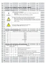
10.1
RS485
This series of inverters provide two RS485 ports. You can monitor one or more inverters via
RS485. The other RS485 port is used to connect a smart meter (stand-alone antibackflow func-
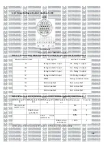
tion).The pin function of the 8-core terminal is the same as the 1-8 pin function of the 1 6-core
terminal.
No. Description
Remarks
1
+ 12V
Dry contact: external relay coil
interface, power is not more
than 2W
2
COM
3
RS485A1
Rs485 communication port
4
RS485B1
5
RS485A2
BAT communication port(re-
served)
6
RS485B2
7
RS485A3
Meter communication port
8
RS485B3
9
Relay contact
1 /DRM 5
Relay contact 1 input/DRM5
command
10 Relay contact
2/DRM 6
Relay contact 2 input/DRM6
command
11 Relay contact
3 /DRM 7
Relay contact 3 input/DRM7
command
12 Relay contact
4/DRM 8
Relay contact 4 input/DRM8
command
13 REF/GEN
Relay&DRM signal reference
14 DRMO/COM DRM0 common node
Fig 10.2 just for Vietnam models
No. Description
Remarks
1 RS485A1
RS485
communication
port
2 RS485B1
3 RS485A2
Meter
communication
port
4 RS485B2
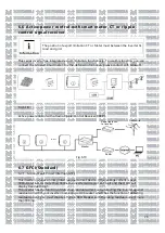
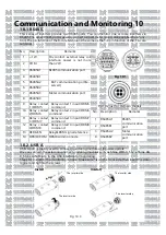
10.2
USB-A
USB-A port is mainly used to connect monitoring module or firmware update :
We can connect the external optional monitoring modules
f
such as Shine WIFI-X, Shine Shine 4G-
X, Shine LAN-X, etc. to the USB interface for monitoring.
Steps for installing the monitoring module: Make sure
A
is on the front side, then insert the data-
logger and tighten the screws.
Install
Unistall
Fig 10.1
The inverter side
The inverter side
The inverter side
The inverter side
up
Fig 10.3
Содержание MOD 1 0KTL3-X
Страница 1: ...Asennus ja k ytt ohje...
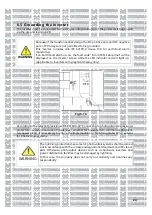
Страница 19: ...Kuva 5 9 Kaaviokuva invertterin sein asennuksesta 15...
Страница 60: ...Installations och bruksanvisning...
Страница 78: ...Figur 5 9 Schema f r v ggmontering av v xelriktaren 15...
Страница 119: ...Kontaktuppgifter 19 Suomi Trading Oy Areenakatu 7 37570 Lemp l asiakaspalvelu suomitrading fi...
Страница 120: ...Installation Operation Manual...
Страница 138: ...Fig 5 9 Schematic diagram of inverter wall mounting 15...
Страница 179: ...Contact us 19 Suomi Trading Oy Areenakatu 7 37570 Lemp l asiakaspalvelu suomitrading fi 56...
Страница 180: ......


