background image

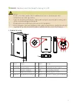
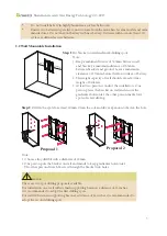
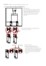
There are two spot drilling proposals available.
For installation on a wall with its main supporting beams at a distanceof 16 inches, 
it is recommended to adopt the first drilling spots.
For wall with its main supporting beam at a distance of 24 inches, it is recommended to 
adopt the second drilling spots.

* 

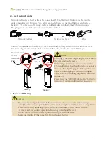
Do not install battery in highly humid area such as bathroom.

* 

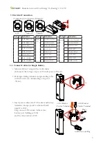
Ensure two batteries in parallel connection are from the same batch, same model and same      

              manufacturer. Do not mix old battery with new battery. Batteries with no more than 300               
              cycles are defined as new batteries.

2.2 Wall Mountable Installation

Step 1

:Put bracket on wall and mark drilling spots

Note:
1. Keep a minimal distance of 320mm between wall 
     and bracket; a maximum distance of 765mm 
     between bracket and ground. Leave a minimum 
     clearance of 133mm before the front surface of battery.
2. The weight capacity of wall should exceed 4 times  
     weight of batteries.
3. At least two persons conduct the installation.  One 
     person places the bracket on wall and ensure the 
     gradienter horizontal; the other person marks four 
     spots of screw driving.
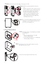
Step 2

: Drill in the spots for at least 60mm. Clean the soil and drive expansion tube into the hole.

Note: 
1. Choose alloy drill bit with a diameter of 12mm.
2. One person puts the bracket on wall and minds to keep gradienter horizontal. 
    The other person drives M8 screw through the bracket into holes.

3

320mm

320mm

765mm

!

CAUTION 

Proposal 2

Proposal 1

Shenzhen Growatt New Energy Technology CO.,LTD

Содержание GBLI6532

Страница 1: ...GBLI6532 Battery System Quick Installation Guidance ...

Страница 2: ...mpliance with storage transportation installation and usage requirements specified in Quick Guidance and Manual are not coved by Warranty CAUTION 1 Product Overview LED 1 LED 2 LED 4 LED 5 LED 3 2 1 3 4 5 6 7 8 1 475 765 150 148 745 No label Name No label Name 1 POWER Power button 5 Link out Parallel Network Output 2 Positive terminal 6 Grounding terminal 3 _ Nagative terminal 7 PCS Network port t...

Страница 3: ...or use battery near explosive or inflammable substances Use battery in well ventilated environment with temperature ranging from 10 to 50 For outdoor installation build sun rain shade to avoid direct sunlight and rain exposure Do not place battery upside down nor alongside as the above picture shown Maintain a minimum level of dust and dirt in the environment CAUTION 2 θ 5 θ 5 Wall Wall Wall Groun...

Страница 4: ... drilling spots Note 1 Keep a minimal distance of 320mm between wall and bracket a maximum distance of 765mm between bracket and ground Leave a minimum clearance of 133mm before the front surface of battery 2 The weight capacity of wall should exceed 4 times weight of batteries 3 At least two persons conduct the installation One person places the bracket on wall and ensure the gradienter horizonta...

Страница 5: ...urface of battery Step 2 Drill in the spots for at least 60mm Clean the soil and drive expansion tube into hole 4 Drive M8 screw through notch of latch into wall Step 3 Fix battery on bracket from the top down Note In order to guarantee a stable connect between battery and bracket please visually check if the two upper joints are fixed Try to move the lower part of battery away from wall The conne...

Страница 6: ...6 GND ISO 7 GND ISO 8 WKP OUT 3 1 Connect Cables for Single Battery 1 Measure battery voltage with a multi meter and ensure the voltage output is 0V under power off mode 2 Fasten grounding terminal and grounding cable with M6 screw recommending a torque of 5N m 3 Insert power cables into DC Breaker and battery terminals orange positive cable and black negative cable Plug one end of Network Cable A...

Страница 7: ...ERTER 300 d 500 300 d 500 6 2 Fasten ground terminal and grounding cable with M6 screw for two batteries 3 Insert power cables Plug one end of power cables into DC breaker Measure the positive and negative terminal blocks of each battery with a multi meter and ensure the voltage outputs under off mode are all 0V After that plug the other end of power cables into battery terminals to PCS Positive T...

Страница 8: ...hnical knowledge is involved in the electrification process and electricians must go through technical training and obtain certificates in compliance with local law and regulations Please stand on dry insulating objects and do not wear metal objects such as watches necklaces and rings during operation Insulating tools should be used Do not contact with two charged positions with potential differen...

Страница 9: ...us PCS HMI screen indicates normal PV or mains supply input Single Battery Power on battery by pressing POWER button Power on battery by Activating PCS Procedures Acceptation criteria Procedures Acceptation criteria 1 Close the breaker from battery to converter Breaker in ON status 1 Close the breaker from battery to converter Breaker in ON status 2 Press POWER button for two seconds and observe t...

Страница 10: ...Address No 28 Guangming Road Shiyan Street Bao an District Shenzhen P R China Press the POWER button of any battery for two seconds Five LED lights will flicker for three times and battery turns off Battery will turn off 25 minutes after Network Cable A connection between PCS and PACK fails 5 2 Power off Battery ...

Отзывы: