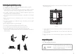
background image

16

15

Installation

5.1 Safety instruction

All electrical installations shall be done in accordance with the local and national                        
electrical  codes.  Do  not  remove  the  casing.  Inverter  contains  no  user  serviceable       
parts.  Refer  servicing  to  qualified  service  personnel.  All  wiring  and  electrical       
installation should be conducted by a qualified service personnel.

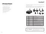
Carefully  remove  the  unit  from  its  packaging  and  inspect  for  external  damage.  If 
you find any imperfections, please contact your local dealer.

Be sure that the inverters connect to the ground in order to protect property and 
personal safety.

The  inverter  must  only  be  operated  with  PV  generator.  Do  not  connect  any  other 
source to it.

Both  AC  and  DC  voltage  sources  are  terminated  inside  the  PV  Inverter.  Please 
disconnect these circuits before servicing.

This unit is designed to feed power to the public power grid (utility) only. Do not 
connect  this  unit  to  an  AC  source  or  generator.  Connecting  Inverter  to  external 
devices could result in serious damage to your equipment.

When  a  photovoltaic  panel  is  exposed  to  light,  it  generates  a  DC  voltage.  When 
connected  to  this  equipment,  a  photovoltaic  panel  will  charge  the  DC  link 
capacitors. 

Energy  stored  in  this  equipment’s  DC  link  capacitors  presents  a  risk  of  electric 
shock. Even after the unit is disconnected from the grid and photovoltaic panels, 
high voltages may still exist inside the PV-Inverter. Do not remove the casing until 
at least 5 minutes after disconnecting all power sources.

Although  designed  to  meet  all  safety  requirements,  some  parts  and  surfaces  of 
Inverter are still hot during operation. To reduce the risk of injury, do not touch the 
heat  sink  at  the  back  of  the  PV-Inverter  or  nearby  surfaces  while  Inverter  is 

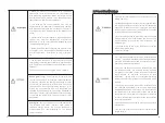
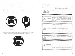
Danger to life due to fire or explosion 

> Despite careful construction, electrical devices can cause fires.

>  Do  not  install  the  inverter  on  easily  flammable  materials  and 
where flammable materials are stored.

Risk of burns due to hot enclosure parts

Mount  the  inverter  in  such  a  way  that  it  cannot  be  touched 
inadvertently.

Possible damage to health as a result of the effects of radiation!

In special cases, there may still be interference for the specified 
application area despite maintaining standardized emission limit 
values  (e.g.  when  sensitive  equipment  is  located  at  the  setup 
location  or  when  the  setup  location  is  near  radio  or  television 
receivers).In  this  case,  the  operator  is  obliged  to  take  proper 
action to rectify the situation.

Never  install  the  inverter  near  the  sensitive  equipment

  (

e.g. 

Radios, telephone, television, etc

)

Do  not  stay  closer  than  20  cm  to  the  inverter  for  any  length  of 
time unless it is absolutely necessary.

Growatt  assumes  no  responsibility  for  compliance  to  EMC 
regulations for the  complete system

Содержание 30000 TL3

Страница 1: ...LTD 1st East 3rd Floor Jiayu Industrial Zone Xibianling Shangwu Village Shiyan Baoan District Shenzhen P R China 86 755 2747 1900 86 755 2749 1460 info ginverter com Www ginverter com T F E W GR UM 0...

Страница 2: ...or fitness for any particular purpose All such warranties are expressly disclaimed Neither Shenzhen Growatt New Energy Technology Co Ltd nor its distributors or dealers shall be liable for any indirec...

Страница 3: ...PPT of the Growatt TL3 6 6 Communication Start up and Shut down the inverter 7 7 1 Start Up the inverter 7 2 Shut down the Inverter Maintenance and Cleaning 8 Trouble shooting 9 10 1 Dismantling the I...

Страница 4: ...o observe these instructions For possible changes in this manual SHENZHEN GROWATT NEW ENERGY TECHNOLOGY CO LTD accepts no responsibilities to inform the users 1 1 3 Storage of the manual 1 1 4 Additio...

Страница 5: ...ains Growatt TL3 series inverters or any other Growatt inverters the system designing software ShineDesign download from site www ginverter com will provide adequate supports AC Abbreviation for Alter...

Страница 6: ...Assembly Warnings absence of any transport or handling damage which could affect insulation integrity or safety clearances failure to do so could result in safety hazards Unauthorized removal of nece...

Страница 7: ...watt TL3 series inverters need install a separate energy meter The energy produced is compensated at a rate depending on the electric power company 2 5 Operation Warnings during operation Although des...

Страница 8: ...of connection for grounding protection Operation after 5 minutes Direct Current DC Alternating Current AC EU waste electrical and electronic equipment WEEE label Product Description 3 3 1 Inverter ove...

Страница 9: ...discover any visible damage to the inverter We will be glad to assist you if required When transporting the inverter the original or equivalent packaging should to be used and the maximum layers for o...

Страница 10: ...RF Ethernet Wi Fi Wide PV voltage range 180V 1000V The maximum efficiency is 98 2 IP65 environmental protection Remote update capability Easy to install Fig 4 1 Item A B C D E F G H I Quantity 1 1 1...

Страница 11: ...after the unit is disconnected from the grid and photovoltaic panels high voltages may still exist inside the PV Inverter Do not remove the casing until at least 5 minutes after disconnecting all pow...

Страница 12: ...verter should be 25 60 The installation location must be freely and safely to get at all times Vertically installation and make sure the connection of inverter must be downwards Never install horizont...

Страница 13: ...he bracket is firmly mounted on the wall then mount the inverter on the bracket Rise up the Growatt TL3 a little higher than the bracket Considering the weight of Growatt TL3 you need to hang on the i...

Страница 14: ...n or snow to extend the inverter service life despite the IP65 protection degree Exposure to the sunlight may cause additional internal heating which will cause power derating Fig 5 7 Fig 5 8 More tha...

Страница 15: ...rrent in the event of a malfunction in the original protective conductor For installation countries falling within the scope of validity of the IEC standard 62109 you must Installthe protective conduc...

Страница 16: ...verter NEVER connect or disconnect the DC connectors under load Improper operation during the wiring process can cause fatal injury to operator or unrecoverable damage to the inverter Only qualified p...

Страница 17: ...000 TL3 33000 TL3 40000 TL3 Max current 35A 38A 38A 5 In order to seal the inverter all unneeded DC inputs must be closed with sealing plugs Cable requirements 30000 TL3 33000 TL3 40000 TL3 Model 2 05...

Страница 18: ...er should not be connected to PE 5 5 Grid Type 5 5 1 Common grid type For TT grid mode the valid value of the Neutral to PE voltage should be less than 30 V Based on the local GRID standards it may se...

Страница 19: ...Whenever the DC voltage is higher than 300Vdc inverter converts power to grid as generated by the PV panels Whenever the DC voltage is lower than 250Vdc the inverter will work in waiting state and at...

Страница 20: ...played can be changed by knock you can also change some inverter parameters by knock Fig 6 3 1 Fig 6 3 2 Note have been preset in factory and you don t need to operate this step any more If you have o...

Страница 21: ...ht off After the power on information is displayed automatically and the backlight turns off the LCD display will switch to the following Interface 1 There are 4 interfaces which can be displayed in t...

Страница 22: ...aximum energy yield of one hour Power curve The daily energy yield curve 6 3 2 3 Connecting messages When inverter started to connect to grid the following message will appear on LCD screen See Fig6 3...

Страница 23: ...rameters setting First level menu It is a little bit different to enter the first level menu note that using thrice knock to enter first level menu instead of double knock Fig 6 3 14 is the interface...

Страница 24: ...ut current for each MPP tracker PV input power for each MPP tracker Inverter output parameters AC output voltage for each phase AC output current for each phase AC output power for each phase Third le...

Страница 25: ...rd level menu interface of working information State information First level menu Second level items Item explanation No xxxxxxxxxx Model xxxxxxxxxx Main Ver xxxxxx Comm Ver xxxxxx Serial number of th...

Страница 26: ...ly if user saves save the choice by double knock and LCD displays Set OK The inverter provides five languages Italian English German Spanish and French The number on Set language interface is sequence...

Страница 27: ...d bar of the graph represents the current unit of time Day h Week day Month M Year Y The top bar of the graph represents the maximum value of the graph values The daily graph is displayed by default Y...

Страница 28: ...ine switch to the text as follow 2 Knock the enclosure lid twice and the text will show the language 3 You can choose the language by tripping the enclosure once the language includes English Deutsh E...

Страница 29: ...once every time until the text line switch to the text as follow 2 Double knock the enclosure lid and switching to external wireless communication 3 Then knock the enclosure three times to confirm it...

Страница 30: ...nd must not be used for billing purposes The inverter s measurement values are required for the operational control and to control the current to be fed into the electricity grid The inverter does not...

Страница 31: ...6 2 Monitor the inverters The inverter provides RS485 interface and RS232 interface to communicate with remote PC or logger User can monitor the inverter state via the following types of communicatio...

Страница 32: ...Through RS232 interface wireless module Data logger PC Through RS232 interface wireless module Data logger Internet Plan B 57 58...

Страница 33: ...through the hole of cable gland and put the cable into the RS485 terminals fix all cables with screwdriver 1 to 1 3 to 3 2 to the shielding layer or no connection The type of cable is recommended as...

Страница 34: ...ing fans failed Ventilation of installation location is poor Choose appropriate installation location before mounting Maintain fans and heatsink every half a year to reduce the power derating caused b...

Страница 35: ...the fans in reverse order 9 1 Error Messages displayed on LCD An error message will be displayed on the LCD screen when a fault occurs The faults consist of system fault and inverter fault You may be...

Страница 36: ...han 1 M If the error message is displayed despite the above checking passed contact Growatt 1 Restart invert 2 If error message still exists contact Growatt 1 Restart inverter 2 If error message still...

Страница 37: ...Error 117 Error 119 Error 121 GFCI fault Control board has not received data from Communication board for 5S Restart inverter if problem still exist contact Growatt Restart inverter if problem still e...

Страница 38: ...1000V 38A 38A 61 6kg 55 dB A Smart cooling IP 65 Transformerless 2000m without derating 0 100 551 740 276 mm 25 C 60 C with derating above45 C 0 5W Growatt 40000TL3 Datasheet H4 MC4 opt Screw termina...

Страница 39: ...Shine Vision receiver Shine Vision emitter Internal fan of Growatt TL3 Outside fan of Growatt TL3 Communication interface Communication interface Communication data logger Communication data logger re...

Страница 40: ...ter type 2 Modules information 3 Communication method 4 Serial number of Inverters 5 Error code of Inverters 6 Display of inverter Shenzhen Growatt New Energy Technology CO LTD 1st East 3rd Floor Jiay...

Отзывы: