Blade Assembly
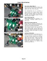
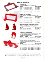
The cutter blades are attached to the blade drive leg by a unique three bolt tri-pad mounting
system which enables the operator to adjust the blade to get an equal thickness across the
width of the cut before finally tightening the blade mounting bolts. The tri-pad mounting
system can also accommodate a variety of blades and attachments. All blades are made
from hardened toughened steel and the sod undercutting blades have an arched cross
section allowing the sod to flow easier over the blade while stiffening the blade to prevent
sagging thereby maintaining thickness across the width of the sod..
The upper end of the blade drive leg clamps onto a sealed bearing spindle contained within a
pivoting-arm and depth lever bracket which enables the blade to be raised and lowered to
set the cutting depth or to raise the blade out of work. The selected cutting depth is locked
securely by two clamp plungers and a locking lever. The blade cutting angle remains
constant at all depths. The cutting angle can be altered by loosening the four jockey-wheel
mounting bracket bolts at the rear of the machine and sliding the jockey wheel bracket up or
down on the slots tilting the chassis and changing the blade cutting angle as indicated by the
pointer and scale beside the bracket.
Rear Wheel Assembly
The pneumatic caster tail wheel is mounted on a bracket attached to the rear of the chassis
by four bolts. A foot lever enables the caster wheel to be locked or allowed to swivel for
straight line or curve cutting. For loading, transportation and storage, the caster wheel
should be locked forward facing the chassis. For cutting the caster wheel should be
positioned facing backwards away from the chassis. The caster wheel mounting bracket can
be adjusted up or down to tilt the chassis altering the blade cutting angle as described in the
Blade Assembly paragraph above.
Chassis Assembly
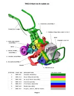
An engine guard is incorporated at the front of chassis. The chassis is designed to allow
access to the mechanisms with the minimum of dismantling. The main sub assemblies can
be removed independently if repairs or maintenance is required. The belt drives are located
external of the chassis and easily accessed by removing the belt covers. The operator
handles are mounted to the chassis by four double jointed circular rubber mounts. These are
positioned and mounted so as to allow maximum deflexion on a vertical plane to absorb
cutting vibrations in work while restricting the right / left or lateral movement for maximum
operator control to steer and guide the machine in the cut. A limit stop is incorporated to
prevent damage to the rubber joints if excessive force is applied the operator handles. The
handles can be folded over the chassis for compact storage.
SEE TMC26 PARTS MANUAL FOR EXPLODED PARTS ILLUSTRATIONS AND PART NUMBERS
TMC26 Technical Information
Page 8
Содержание TMC24 TURF multi Cutter
Страница 21: ...Page 18 NOTES www groundsmanindustries com ...


