background image

3

GB

Safety notes

• Installation is only possible in frost-free rooms.
• The plug-in connectors must 

not

 be directly or indirectly 

sprayed with water when cleaning.

Application

Can be used in conjunction with:
•  Pressurised storage heaters
•  Thermally/hydraulically controlled instantaneous water heaters
Operation with unpressurised storage heaters (displacement 
water heaters) is 

not

 possible.

•  The GROHE touch function for switching the water flow on 

or off is based on the principle of electrical charge shifting on 
metallic surfaces. If the solenoid valve is closed during touch 
sensing it will be opened, and if the solenoid valve is already 
open it will be closed.

Specifications

•  Flow pressure:


- min. 

0.05 MPa

- recommended 

0.1 - 0.5 MPa

•  Operating pressure 

max. 1.0 MPa

•  Test pressure    

1.6 MPa

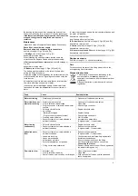
A pressure reducing valve must be fitted in the supply line if 
static pressures exceed 0.5 MPa to satisfy noise level ratings.
Avoid major pressure differences between cold and hot water 
supply! 
• Temperature hot water inlet: 

max. 70 °C

Recommended (energy saving):

 60 °C

• Thermal desinfection possible
•  Ambient temperature:

4 - 40 °C

• Relative humidity: 

max. 80%

• Voltage supply: 

   6 V lithium battery (type CR-P2)

• Rated power:

1.4 W

• Automatic safety shut-off after contact: 

60 s

• Three water pulses indicate that a battery change is 

necessary.

• Type of protection control:


IP 44

•  Water connection 

cold - right

hot - left

Approval and conformity

The conformity declarations can be obtained from the following 
address:

GROHE Deutschland Vertriebs GmbH

Zur Porta 9
D-32457 Porta Westfalica

Installation

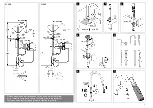
Refer to fold-out page I for hose lengths and installation 
dimensions.

Caution: 

The control should be easily accessible.

Flush pipes thoroughly before and after installation


(observe EN 806).


Install


the fitting,

 see fold-out page I and II, Figs. [1] to [9].

Connecting the faucet

Install bracket with control and connect, 

see fold-out page II, 

Figs. [10] to [14].

Install


weight on shower hose,

 see Fig. [15].

Important note
To ensure proper functioning when using metal sinks, 
the sink must be connected to the control via the pre-
assembled yellow hose for potential equalisation,


see Fig. [16].
For all other sinks the yellow hose must be connected to 
another suitable metal part for potential equalisation.

Country specific and local regulations must be 
observed.

Putting into service

To prevent the risk of scalding, the outlet 
temperature of the mixer unit should be set to 
lukewarm.
Recommended maximum temperature: 38 °C

,

see Fig. [18].

The spout must always be positioned above the 
sink to prevent water damage.
Ensure free runoff.

Insert battery, 

see fold-out page II, Figs. [17] - [20].

The sequence is important and must be observed.

The electronics will detect ambient conditions. During this time 
the control indicator lamp flashes. The fitting must 

not

 be 

activated (for approx. 1 min.).

Check connections for watertightness.
Check for proper function

, see Fig. [21].

Adjusting 

of touch parameters to ambient conditions, 

see fold-out page III, Fig. [22].
- The release varies depending on ambient temperature 

and air humidity. 

- Touch parameters: 5 highest value... 1 lowest value...
- A value that is too high leads to the risk of continuous 

operation. 

The menu is started by pressing the button at the control unit 
for at least 10 seconds.
•  The indicator lamp flashes once.
•  The last stored value will then be displayed by flashing, 

e.g. three times for level 3 (factory setting).

•  Each time the button is pressed the value goes up one level.
•  The selected level is indicated by the number of flashes.
- If no further buttons are pressed, the indicator lamp signals 

the last set value 2 more times. The lamp then emits a 
continuous signal and the menu is exited. The last stored 
value will be saved. 

Operation,

 see fold-out page III, Figs. [23] to [26].

By touching the areas depicted in

 grey

 water can be drawn 

without using the lever, see Fig. [23].

Note:

 Activation only by skin contact.

If the flow rate in the touch function is too high, exchange non-
return valve 08 565 with 64 689, see fold-out page II, Fig. [13] 
and fold-out page IV. 

Shower jet diverter 

see Fig. [26].

Flow rate limitation,

 see Fig. [27] and [28].

Cleaning mode,

 see Fig. [29].

Cleaning mode is started by grabbing the faucet for more than 
5 seconds.
•  Confirmation via a water pulse. 
•  In cleaning mode (approx. two minutes) the indicator lamp 

flashes twice at the beginning and twice at the end of the 
cleaning mode cycle.

Hygiene flushing

, see Fig. [30].

Hygiene flushing serves to ensure water hygiene if the fitting is 
not used for a long time.

This product conforms to the requirements of the 
relevant EU guidelines.

Содержание MintaTouch 31 358

Страница 1: ...14 SLO 19 LT 24 I 5 FIN 10 H 15 HR 20 RO 25 DESIGN ENGINEERING GROHE GERMANY www grohe com D 1 NL 11 PL 21 P 31 BG 41 CN 51 GB 3 S 13 UAE 23 TR 33 EST 43 UA 53 F 5 DK 15 GR 25 SK 35 LV 45 RUS 55 E 7...

Страница 2: ...75 min 60 2 7 6 max 60 3 S v p remettre cette instruction l utilisateur de la robinetterie Entregue estas instrucciones al usario final de la grifer a Please pass these instructions on to the end use...

Страница 3: ...II 16 15 19mm 19mm 12 19mm 19mm 19mm 19mm 9 19mm 22mm 22mm 24mm 11 19mm 19mm 8 10 14 1 2 3 13 A B 21 17 18 38 C 38 C 19 20 1min...

Страница 4: ...ung verbunden werden siehe Abb 16 Bei allen anderen Sp len muss die gelbe Leitung f r den Potentialausgleich an ein anderes geeignetes Metallteil angeschlossen werden Hierbei sind die l nderspezifisch...

Страница 5: ...und Sieb siehe Klappseite III Abb 36 Montage in umgekehrter Reihenfolge Ersatzteile Siehe Klappseite IV Sonderzubeh r Pflege Die Hinweise zur Pflege dieser Armatur sind der beiliegenden Pflegeanleitun...

Страница 6: ...e connected to another suitable metal part for potential equalisation Country specific and local regulations must be observed Putting into service To prevent the risk of scalding the outlet temperatur...

Страница 7: ...ections on the care of this fitting please refer to the accompanying Care Instructions Disposal instructions This category of device does not belong in the domestic waste but must be disposed of separ...

Страница 8: ...onnement voir fig 16 Pour tous les autres viers le c ble jaune doit tre connect un autre l ment en m tal appropri pour la liaison quipotentielle ce stade il faut veiller respecter les conditions sp ci...

Страница 9: ...nverse de la d pose Pi ces de rechange Voir volet IV accessoires sp ciaux Entretien Les consignes d entretien de cette robinetterie figurent dans les instructions d entretien ci jointes Remarque sur l...

Страница 10: ...l nea amarilla con el mando si se utiliza un fregadero met lico para la conexi n equipotencial v ase la fig 16 En todos los dem s fregaderos para la conexi n equipotencial se debe conectar una l nea...

Страница 11: ...V lvula antirretorno y tamiz v asela p gina desplegable III fig 36 El montaje se efect a en el orden inverso Piezas de recambio V ase la p gina desplegable IV accesorios especiales Cuidados La informa...

Страница 12: ...mando tramite il cavo giallo premontato al fine di assicurarne il funzionamento vedere fig 16 In caso di utilizzo di un altro tipo di sciacquo per il collegamento equipotenziale necessario collegare i...

Страница 13: ...o Vedere il risvolto di copertina IV accessori speciali Manutenzione ordinaria Le istruzioni per la manutenzione del presente rubinetto sono riportate nelle istruzioni per la manutenzione ordinaria fo...

Страница 14: ...j alle andere spoelbakken moet de gele kabel voor de potentiaalvereffening worden aangesloten op een ander geschikt metalen onderdeel Neem hierbij ook op de nationale en lokale voorschriften in acht I...

Страница 15: ...in omgekeerde volgorde VI Terugslagklep en zeef zie uitvouwbaar blad III afb 36 Montage in omgekeerde volgorde Reserveonderdelen Zie uitvouwbaar blad IV speciaal toebehoren Onderhoud De aanwijzingen v...

Страница 16: ...f rmonterade gula kabeln f r att den ska fungera som den ska se fig 16 F r andra hoar m ste den gula kabeln f r potentialutj m ningen anslutas till annan l mplig metalldel H r g ller landspecifika vil...

Страница 17: ...r Sk tsel Sk tseltips f r denna blandare finns i den bifogade sk tselanvisningen Avfallshanteringsanvisningar Apparater med denna m rkning h r inte hemma bland hush llsavfallet utan m ste avfallshante...

Страница 18: ...ede gule ledning for potentialudligning for at sikre funktionen se ill 16 For potentialudligning af alle andre vaske skal den gule ledning forbindes med en anden egnet metaldel De landsspecifikke beti...

Страница 19: ...af dette armatur kan findes i den medf lgende plejevejledning Anvisninger vedr rende bortskaffelse Apparater med denne betegnelse m ikke bortskaffes sammen med almindeligt affald men skal bortskaffes...

Страница 20: ...ummer m ledningen til potensi alutjevningen v re koblet til en annen egnet metalldel Her m de nasjonale spesifikke betingelsene og lokale forskriftene f lges Igangkj ring For unng sk lding m utgangste...

Страница 21: ...ormasjon om pleie av denne armaturen finnes i vedlagte pleieveiledning Informasjon om kassering Produkter som har denne klassifiseringen m ikke kastes i husholdningsavfallet men m kastes kildesortert...

Страница 22: ...asennetulla keltaisella johdolla ohjausyksikk n ks kuva 16 K ytett ess muita altaita keltainen johto on potentiaalintasausta varten yhdistett v muuhun soveltuvaan metalliosaan T ss yhteydess on noudat...

Страница 23: ...a j rjestyksess Varaosat Ks k nt puolen sivu IV lis tarvike Hoito T m n laitteen hoitoa koskevat ohjeet on annettu mukana olevassa hoito oppaassa H vitysohjeet T ll tunnuksella varustetut laitteet eiv...

Страница 24: ...rys 8 Wa ne Dla zagwarantowania poprawnego dzia ania zlewozmywaki metalowe nale y po czy za czonym przewodem z modu em sterowania w celu wyr wnania potencja u patrz rys 16 W przypadku wszystkich innyc...

Страница 25: ...I rys 36 Monta w odwrotnej kolejno ci Cz ci zamienne Zob strona rozk adana IV akcesoria Piel gnacja Wskaz wki dotycz ce piel gnacji armatury mo na znale w za czonej instrukcji piel gnacji Wskaz wki do...

Страница 26: ...23 UAE...

Страница 27: ...24...

Страница 28: ...70 C 60 C 4 40 C 80 6V CR P2 1 4W 60s 3 IP 44 GROHE Deutschland Vertriebs GmbH Zur Porta 9 D 32457 Porta Westfalica I EN 806 I II 1 9 II 10 14 15 16 38 C 18 II 17 20 1 21 Touch II 22 Touch 5 1 10 1 3...

Страница 29: ...26 2 2 30 10 14 19 I III 31 II III 32 III 14 19 10 Touch IV III 33 34 V III 33 35 VI III 36 IV 2 Touch 5 1 Touch 5 1 Touch 5 1...

Страница 30: ...u vyrovn n p ipojen p edmontovan m lut m kabelem s zen m viz obr 16 U v ech ostatn ch d ez mus b t k potenci lov mu vyrovn n lut kabel p ipojen k jin vhodn kovov sti Zde dodr ujte podm nky v m st inst...

Страница 31: ...o et ov n t to armatury jsou uvedeny v p ilo en m n vodu k dr b Pokyny k likvidaci P stroje s t mto ozna en m nepat do domovn ho odpadu tyto je nutno ve smyslu ekologick ch p edpis p slu n zem odevzda...

Страница 32: ...a 16 br t Minden egy b t lca eset n a potenci lkiegyenl t s miatt a s rga vezet ket egy m sik megfelel f mr szhez kell csatlakoztatni Ek zben be kell tartani az adott orsz gban rv nyes felt teleket s...

Страница 33: ...tkoz utas t sokat a mell kelt pol si tmutat tartalmazza rtalmatlan t sra vonatkoz utas t sok Az ezen jelz ssel ell tott k sz l kek nem helyezhet k a h ztart si hullad kba hanem az adott orsz gban rv n...

Страница 34: ...al de modo a garantir o funcionamento ver fig 16 Em todos os outros lava loi as necess rio que o cabo amarelo seja ligado a outra pe a de metal adequada para a liga o equipotencial Nesse sentido devem...

Страница 35: ...es de conserva o desta misturadora podem ser consultadas no manual de conserva o em anexo Indica es para elimina o Os aparelhos com esta identifica o n o devem ser misturados com o lixo dom stico e t...

Страница 36: ...a lamak zere nceden monte edilmi sar hatla kontrol sistemine ba lanmal d r bkz ek 16 Di er t m bo alt mlarda potansiyel dengeleme i in sar hat uygun olan di er bir metal par as na ba lanmal d r Bu esn...

Страница 37: ...lamayla yap l r Yedek par alar Bkz katlan r sayfa IV zel aksesuar Bak m Bu bataryan n bak m ile ilgili bilgiler i in l tfen birlikte verilen bak m talimat na ba vurun mha uyar lar Bu i aretle s n flan...

Страница 38: ...n s riaden m prostredn ctvom vopred namontovan ho lt ho vedenia pozri obr 16 V pr pade v etk ch ostatn ch v leviek mus by lt vedenie na vyrovn vanie potenci lu pripojen k in mu vhodn mu kovov mu dielu...

Страница 39: ...om porad N hradn diely Pozri skladaciu stranu IV zvl tne pr slu enstvo O etrovanie Pokyny na o etrovanie tejto armat ry s uveden v prilo enom n vode na dr bu Upozornenie k likvid cii odpadu Pr stroje...

Страница 40: ...predname enega rumenega voda s krmiljenjem glejte sl 16 Pri vseh drugih pomivalnih koritih je treba rumeni vod za izravnavo potenciala priklju iti na drug ustrezen kovinski del Pri tem je treba upo t...

Страница 41: ...zlo ljivo stran III sl 36 Monta o izvedite v obratnem vrstnem redu Nadomestni deli Glejte zlo ljivo stran IV dodatna oprema Nega Navodila za nego te armature najdete v prilo enih navodilih za vzdr eva...

Страница 42: ...nja potencijala preko prethodno monitranog utog voda i kako biste se njima mogli koristiti vidi sl 16 Ako upotrebljavate neko drugo korito morate za izjedna avanje potencijala priklju iti uti vod na n...

Страница 43: ...reklopnu stranicu III sl 36 Monta a se obavlja obrnutim redoslijedom Rezervni dijelovi Vidi preklopnu stranicu IV poseban pribor Odr avanje Naputke za odr avanje ove armature mo ete prona i u prilo en...

Страница 44: ...0 5 MPa 70 C 60 C 4 40 C 80 6 V CR P2 1 4 W 60 3 IP 44 GROHE Deutschland Vertriebs GmbH Zur Porta 9 D 32457 Porta Westfalica I EN 806 I II 1 9 II 10 14 15 16 38 C 18 II 17 20 1 21 III 22 5 1 10 1 3 3...

Страница 45: ...42 2 2 2 30 10 II 14 19 I III 31 II III 32 III II 14 19 IV III 33 34 V III 33 35 VI III 36 IV 2 5 1 5 1 5 1...

Страница 46: ...ist kraanikausi kasutamisel peab valamu olema toimimise tagamiseks kaasasoleva kaabli abil juhtseadmega hendatud et potentsiaali htlustada vt joonist 16 K ikide muude valamute puhul peab kollane kaabe...

Страница 47: ...vastupidises j rjekorras Tagavaraosad Vt voldiku lk IV eriosad Hooldamine Segisti hooldusjuhised on kirjas kaasasolevas hooldusjuhendis J tmek itlus Selle t hisega seadmeid ei tohi visata olmepr gi hu...

Страница 48: ...plekt cij ietverto potenci la izl dzin anas vadu dzelten kr s skat 16 att lu Izmantojot cita veida izlietnes potenci la izl dzin anai vads dzelten kr s ir j pievieno citai piem rotai met la deta ai To...

Страница 49: ...un siets skatiet III atv ruma 36 att lu Lai saliktu veiciet min t s darb bas pret j sec b Rezerves da as Skatiet IV atv rumu speci lie piederumi Apkope Nor d jumus par s armat ras kop anu skatiet komp...

Страница 50: ...eikia sujungti su valdikliu naudojant i anksto sumontuot gelton laid kad b t u tikrintas veikimas r 16 pav Visose kitose kriaukl se potencialams i lyginti gelton laid reikia prijungti prie kitos tinka...

Страница 51: ...s dalys r IV atlenkiam j puslap special s priedai Prie i ra io mai ytuvo prie i ros nurodymai pateikti prid toje prie i ros instrukcijoje Nuorodos d l utilizavimo iuo enklu pa ym t rengini negalima i...

Страница 52: ...ermediul cablului galben preinstalat a se vedea fig 16 Pentru toate celelalte tipuri de chiuvete pentru a realiza echilibrarea poten ialului cablul galben trebuie conectat la o component metalic adecv...

Страница 53: ...a pagina pliant III fig 36 Se monteaz n ordine invers Piese de schimb A se vedea pagina pliant IV accesorii speciale ngrijirea Indica iile de ngrijire pentru aceast baterie se g sesc n instruc iunile...

Страница 54: ...0 5 MPa 70 C 60 C 4 40 C 80 6 V CR P2 1 4 W 60 IP 44 GROHE Deutschland Vertriebs GmbH Zur Porta 9 D 32457 Porta Westfalica I EN 806 I II 1 9 II 10 14 15 16 38 C 18 II 17 20 1 21 III 22 5 1 10 3 3 2 I...

Страница 55: ...52 30 10 II 14 19 I III 31 II III 32 III II 14 19 10 IV III 33 34 V III 33 35 VI III 36 IV 2 5 1 5 1 5 1...

Страница 56: ...C 60 C 4 40 C 80 6 CR P2 1 4 60 3 IP 44 GROHE Deutschland Vertriebs GmbH Zur Porta 9 D 32457 Porta Westfalica EN 806 I II 1 9 10 14 15 16 38 C 18 II 17 20 1 21 Touch III 22 Touch 5 1 10 1 3 III 23 26...

Страница 57: ...54 30 10 II 14 i 19 I 31 II III 32 II II 14 i 19 10 Touch IV III 33 34 V III 33 35 VI III 36 IV 2 Touch 5 1 Touch 5 1 Touch 5 1...

Страница 58: ...M 70 C 60 C 4 40 C 80 6 CR P2 1 4 60 3 IP 44 GROHE Deutschland Vertriebs GmbH Zur Porta 9 D 32457 Porta Westfalica I EN 806 I II 1 9 II 10 14 15 16 38 C 18 II 17 20 1 21 Touch III 22 Touch 5 1 10 1 3...

Страница 59: ...56 2 2 2 30 10 II 14 19 I III 31 II III 32 III II 14 19 10 IV III 33 34 V III 33 35 VI III 36 IV 2 Touch 5 1 Touch 5 1 Touch 5 1...

Страница 60: ......

Страница 61: ......

Страница 62: ...II 22 10 sec 23 24 38 C 38 C 26 3mm 27 2 5mm 28 29 2min 5sec 30 10min 3mm 31 32 34 35 36 19mm 22mm 24mm 22mm 64 689 08 565 III 19mm 24mm 33 25...

Страница 63: ...II IV...
Страница 64: ...he com LT 372 6616354 grohe grohe ee LV 372 6616354 grohe grohe ee MAL info malaysia grohe com MX 01800 8391200 pregunta grohe com N 47 22 072070 grohe grohe no NL 31 79 3680133 vragen nl grohe com NZ...

Отзывы: