1
English
Application
Pot fillers are designed for delivering cold water from a
main supply. Pot fillers can be positioned above sinks
or stoves and the articulated nature of the spout
enables the outlet to be conveniently positioned above
pots / pans as required.
Specifications
•
Min. flow rate
15 L/min or 4 gpm / 20 psi
•
Flow pressure
- min.
7.25 psi
- recommended
14.5 - 72.5 psi
- greater than 72.5 psi, fit pressure reducing valve
•
Max. operating pressure
145 psi
•
Test pressure
232 psi
Installation
Note:
When installing e. g. on plasterboard walls (not solid
walls) it must be assured that an appropriate rein-
forcement is in place to ensure sufficient strength.
Flush pipes thoroughly!
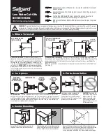
Mount pot filler
Refer to the dimensional drawing on fold-out page I
and fold-out page II, fig. [1].
1. Push flange (A) on pot filler (B), see fig. [2].
2. Screw on pot filler (B) with flange (A) by using
an 25mm open-ended wrench and layout holes for
fastening.
3. Drill holes and insert plugs (C), see fig. [3].
4. Fasten flange (A) and seal (D) to the wall by using
the screws (E), see fig. [4].
5. Cover flange (A) with escutcheon (F).
6. Screw in screw (F1) by using an 1.5mm allen
wrench to fasten escutcheon (F) to flange (A).
7. Screw on pot filler (B) by using an 25mm open-
ended wrench, see fig. [5].
8. Screw in screw (B1) by using an 3mm allen wrench,
level with spirit level and fasten flange to pot filler.
Open water supply and check connections for
leakage!
Operation
For ease of use the pot filler is fitted with two head-
parts.
If the pot filler is to be left unattended ensure both
ceramic cartridges are left in the closed position.
IMPORTANT:
NOT FOR USE AS A FIRE EXTINGUISHER!
Maintenance
Inspect and clean all parts, replace as necessary and
grease with special grease.
Shut off water supply!
I. Replacing the ceramic cartridge,
see fig. [6].
1. Unscrew cap (G) and pull off shut-off handle (H)
complete.
2. Unscrew ceramic cartridge (J) by using a 17mm
socket wrench and remove O-ring (K).
3. Change complete ceramic cartridge (J) or
O-ring (J1) and reinstall O-ring (K).
II. Hinged sockets,
see fig. [6].
1. Unscrew pot filler arm (L).
2. Unscrew hinged socket (M) by using an 10mm
allen wrench.
III. Flow control,
see fold-out page I.
Unscrew and clean flow control (13 983).
Assemble in reverse order.
Observe the correct installation position!
Replacement parts,
see fold-out page I ( * = special
accessories).
Care
Instructions for care of this faucet will be found in the
Limited Warranty supplement.