OM-TDB/7
5
Equipment Description
The Groen TDB/7 is a table top, tilting, steam
jacketed kettle with a thermostatically controlled,
self-contained, electrically-heated steam supply and
appropriate controls, mounted on a sturdy base. The
Model TDB/7 is available in 20 or 40 - quart capacity.
The body of the TDB/7 Kettle is constructed of
stainless steel, welded into one solid piece. The
kettle is furnished with a reinforced rim and a
butterfly shaped pouring lip. It has a steam jacket
rated for working pressures up to 50 PSI. Kettle
finish is 180 emery grit on the inside and bright semi-
deluxe on the outside. A tilt handle allows the
operator to manually tilt the kettle body in a
controlled manner. Pouring height accepts pans up to
4 inches high on a table top.
A built-in steam generator, sized for the kettle
capacity and heated by electricity, delivers steam
into the jacket. “Airless” operation of the steam
jacket permits uniform, efficient heating at
temperatures as low as 150°F and as high as 295°F.
In addition to the adjustable thermostat for operating
control, the unit has a tilt cut-off switch, low water
cut-off, safety valve, and high-limit pressure switch
as safety features. A heating indicator light,
pressure gauge, and sight glass are provided for
monitoring kettle operation.
A single electrical connection is required for
installation. The unit may be ordered for use with
208/240 or 480 volt power. All kettles are wired for
three-phase operation. For single-phase conversion,
see the wiring diagrams in this manual.
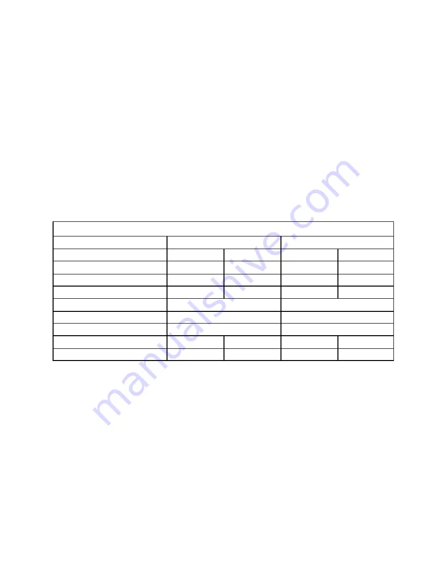
KETTLE CHARACTERISTICS
TDB/7-20+
TDB/7-40
Kettle Capacity
20 qts.
18.8 liters
40 qts.
37.6 liters
Jacket Capacity
4 qts.
3.7 liters
5 qts.
4.7 liters
Diameter
14”
36 cm
16-1/2”
42 cm
Depth
11”
28 cm
14-1/4”
36 cm
K.W. at 208 V
6.3
10.8
K.W. at 240 V
8.4
14.4
K.W. at 480 V
6.3
12.0
Base Width
24”
60 cm
24”
60 cm
Base Depth
16”
41 cm
16”
41 cm
Содержание OM-TDB/7
Страница 15: ...OM TDB 7 15 ...
Страница 21: ...OM TDB 7 21 For units manufactured before September 1 1998 ...
Страница 23: ...OM TDB 7 23 For units manufactured between September 1 1988 and July 1 1992 ...
Страница 25: ...OM TDB 7 25 For units manufactured between July 1 1992 and February 6 1995 ...
Страница 30: ...OM TDB 7 30 Wiring Diagrams For units manufactured before September 1 1988 ...
Страница 31: ...OM TDB 7 31 Wiring Diagrams For units manufactured before September 1 1988 ...
Страница 32: ...OM TDB 7 32 Wiring Diagrams For units manufactured before September 1 1988 ...
Страница 33: ...OM TDB 7 33 Wiring Diagrams For units manufactured after September 1 1988 and before June 1 1990 ...
Страница 34: ...OM TDB 7 34 Wiring Diagrams For units manufactured after September 1 1988 and before June 1 1990 ...
Страница 35: ...OM TDB 7 35 Wiring Diagrams For units manufactured after September 1 1988 and before June 1 1990 ...
Страница 36: ...OM TDB 7 36 Wiring Diagrams For units manufactured after June 1 1990 and before July 1 1992 ...
Страница 37: ...OM TDB 7 37 Wiring Diagrams For units manufactured after June 1 1990 and before February 6 1995 ...
Страница 38: ...OM TDB 7 38 Wiring Diagrams For units manufactured after July 1 1992 and before February 6 1995 ...
Страница 41: ...41 OM TDB 7 TDB 7 20 TDB 7 40 480 VOLT 1 3 PHASE Wiring Diagrams For units manufactured after Feb 6 1995 ...


