OM-TDB/7
13
The pressure gauge should show a vacuum
of 20 to 30 inches when the kettle is cold.
Maintenance
NOTICE: Contact Groen or an authorized Groen representative when repairs are required.
1.
Periodic Maintenance
A Maintenance & Service Log is provided at
the back of this manual with the warranty
information. Each time maintenance is
performed on your Groen kettle, enter the
date on which the work was done, what was
done, and who did it. Keep this manual on
file and available for operators to use.
Periodic inspection will minimize equipment
down time and increase the efficiency of
operation. The following points should be
checked:
[BY OPERATOR]
a.
Check the pressure/vacuum gauge every
day. The gauge should show a vacuum
of 20 to 30 inches, when the kettle is
cold. If it does not, see “Jacket Vacuum”
on page 10.
b.
Also check the jacket water level on a
daily basis. It should be above mid point
of round sight glass (new models) or
between the marks on the gauge glass
(old models). If the level is low, see
“Jacket Filling and Water Treatment” on
page 14.
[BY SERVICE TECHNICIAN]
c.
Electrical wiring should be kept securely
connected and in good condition.
d.
The inside of the support housing should
be kept clean.
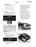
Test the safety valve at least twice each
month. Test the valve with the kettle
operating at 15 psi (105 kPa), by holding the
test lever for at least 5 seconds. Then
release the lever and let the valve snap shut.
If the lever does not activate, or there is no
evidence of discharge, or the valve leaks,
immediately discontinue use of the kettle and
contact a qualified Groen service
representative.
WARNING
WHEN TESTING, AVOID ANY EXPOSURE
TO THE STEAM BLOWING OUT OF THE
S AF E T Y VALVE. DIRECT CONT AC T
COULD RESULT IN SEVERE BURNS.
DISCONNECT ELECTRICAL POWER FROM
THE KETTLE BEFORE ATTEMPTING TO
GREASE THE TRUNNION BEARINGS.
At least twice a year, grease the two
trunnion bearings. The bearings are located
within the kettle support housing. Remove
the access panels from the support housing
with a screwdriver to gain access to the
grease fittings. Use a lithium-based, multi-
purpose grease. When the access panels
are removed, the mounting bolts for the
trunnion bearings and tilt switch can also be
checked for tightness. When finished,
reassemble access panels to support
housing.
2.
Jacket Vacuum
When the kettle is cold, a positive pressure
reading or a reading around zero on the
pressure/vacuum gauge indicates the
presence of air in the jacket. Air in the jacket
slows down the heating of the kettle.
To remove air:
a.
Start the unit. (See the “Operation”
section of this manual.) (Be sure there is
water or product in the kettle when
heating).
b.
When the pressure/vacuum gauge
reaches a positive pressure reading of 5
PSI, release the trapped air and steam
by pulling up or out on the safety valve
Содержание OM-TDB/7
Страница 15: ...OM TDB 7 15 ...
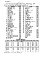
Страница 21: ...OM TDB 7 21 For units manufactured before September 1 1998 ...
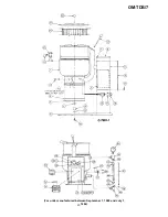
Страница 23: ...OM TDB 7 23 For units manufactured between September 1 1988 and July 1 1992 ...
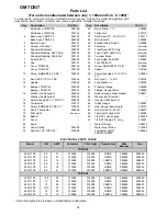
Страница 25: ...OM TDB 7 25 For units manufactured between July 1 1992 and February 6 1995 ...
Страница 30: ...OM TDB 7 30 Wiring Diagrams For units manufactured before September 1 1988 ...
Страница 31: ...OM TDB 7 31 Wiring Diagrams For units manufactured before September 1 1988 ...
Страница 32: ...OM TDB 7 32 Wiring Diagrams For units manufactured before September 1 1988 ...
Страница 33: ...OM TDB 7 33 Wiring Diagrams For units manufactured after September 1 1988 and before June 1 1990 ...
Страница 34: ...OM TDB 7 34 Wiring Diagrams For units manufactured after September 1 1988 and before June 1 1990 ...
Страница 35: ...OM TDB 7 35 Wiring Diagrams For units manufactured after September 1 1988 and before June 1 1990 ...
Страница 36: ...OM TDB 7 36 Wiring Diagrams For units manufactured after June 1 1990 and before July 1 1992 ...
Страница 37: ...OM TDB 7 37 Wiring Diagrams For units manufactured after June 1 1990 and before February 6 1995 ...
Страница 38: ...OM TDB 7 38 Wiring Diagrams For units manufactured after July 1 1992 and before February 6 1995 ...
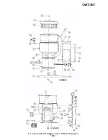
Страница 41: ...41 OM TDB 7 TDB 7 20 TDB 7 40 480 VOLT 1 3 PHASE Wiring Diagrams For units manufactured after Feb 6 1995 ...


