Grizzly T31739 Скачать руководство пользователя страница 41

Model T31739 (Mfd. Since 11/19)

-39-

BUY PARTS ONLINE AT GRIZZLY.COM!

Scan QR code to visit our Parts Store.
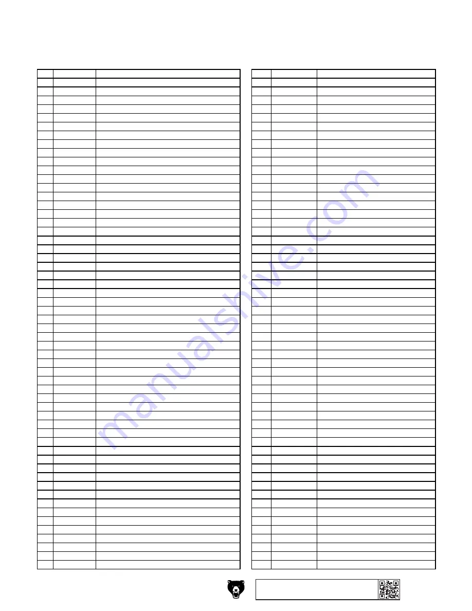
REF PART #

DESCRIPTION

REF PART #

DESCRIPTION

1

PT31739001

BASE

58

PT31739058

HEX NUT M12-1.75

2

PT31739002

COLUMN SEAT

59

PT31739059

RETURN SPRING COVER

3

PT31739003

HEX BOLT M8-1.25 X 20

60

PT31739060

FLAT COIL SPRING

4

PT31739004

COLUMN

61

PT31739061

HEADSTOCK

5

PT31739005

RACK

62

PT31739062

CAP SCREW M8-1.25 X 12

6

PT31739006

REVOLVING HANDLE 20 X 75, M10-1.5 X 10

63

PT31739063

FLAT WASHER 8MM

7

PT31739007

SET SCREW M6-1 X 10

64

PT31739064

COMPRESSION SPRING 2 X 22 X 80

8

PT31739008

LOCK HANDLE 15 X 78, M10-1.5 X 25

65

PT31739065

SPEED SHAFT

9

PT31739009

WORM SHAFT

66

PT31739066

LED BULB 1W 3.5V

10

PT31739010

WORM GEAR PIN

67

PT31739067

LASER DKLD 1801

11

PT31739011

WORM GEAR

68

PT31739068

LASER COVER

12

PT31739012

WORM GEAR HOUSING

69

PT31739069

PINION GEAR

13

PT31739013

COLUMN RING

70

PT31739070

DOWNFEED LEVER HUB M10-1.5

14

PT31739014

HEX BOLT M12-1.75 X 25

71

PT31739071

KNOB BOLT M10-1.5 X 10, D40, ROUND

15

PT31739015

TABLE MOUNTING ARM

72

PT31739072

LASER SEAT

16

PT31739016

TABLE

73

PT31739073

SET SCREW M6-1 X 10

17

PT31739017

EXTENSION ROD 1/2" X 8-3/4"

74

PT31739074

HEX BOLT M10-1.5 X 40

18

PT31739018

KNOB BOLT M8-1.25 X 18, D36, WING

75

PT31739075

FLAT WASHER 10MM

19

PT31739019

EXTENSION ROLLER BRACKET

76

PT31739076

MOTOR MOUNT PLATE

20

PT31739020

EXTENSION ROLLER

77

PT31739077

HEX BOLT M8-1.25 X 16

21

PT31739021

FLAT HD CAP SCR M6-1 X 12

78

PT31739078

MOTOR 1/3HP 120V 1-PH

22

PT31739022

CAP SCREW M10-1.5 X 20

78-1

PT31739078-1 MOTOR FAN COVER

23

PT31739023

DRILL CHUCK JT3 X 1/32"-5/8" KEYLESS

78-2

PT31739078-2 MOTOR FAN

24

PT31739024

DRILL CHUCK ARBOR 5/8"

78-3

PT31739078-3 CAPACITOR COVER

25

PT31739025

SPINDLE

78-4

PT31739078-4 S CAPACITOR 24M 250V 40 X 90

26

PT31739026

BALL BEARING 6204ZZ

78-5

PT31739078-5 MOTOR JUNCTION BOX

27

PT31739027

QUILL

78-6

PT31739078-6 BALL BEARING 6203ZZ

28

PT31739028

BALL BEARING 6201ZZ

78-7

PT31739078-7 MOTOR CORD 3G 3W 39"

29

PT31739029

CLAMP BOLT M12-1.75 X 2

79

PT31739079

HEX NUT M10-1.5

30

PT31739030

COMPRESSION SPRING 1.2 X 6

80

PT31739080

KEY 4 X 4 X 80 SE

31

PT31739031

LOCK NUT M8-1.25

81

PT31739081

MOTOR SPRING SEAT

32

PT31739032

QUICK-RELEASE DEPTH STOP

82

PT31739082

COMPRESSION SPRING 2 X 33 X 78

33

PT31739033

DEPTH STOP SUPPORT NUT

83

PT31739083

MOTOR PULLEY SET

34

PT31739034

THREADED DEPTH ROD

84

PT31739084

SET SCREW M6-1 X 10

35

PT31739035

HEX NUT M6-1

85

PT31739085

PHLP HD SCR M4-.7 X 16

36

PT31739036

DEPTH STOP BRACKET

86

PT31739086

EXT RETAINING RING 16MM

37

PT31739037

CAP SCREW M6-1 X 20

87

PT31739087

SPEED SENSOR MOUNT

38

PT31739038

PHLP HD SCR M5-.8 X 16

88

PT31739088

FLAT WASHER 5MM

39

PT31739039

ROCKER SWITCH GORBO XCK-017 10(4)A 250V

89

PT31739089

PHLP HD SCR M5-.8 X 20

40

PT31739040

MAG ON/OFF SWITCH DKLD DZ04 10A 120V

90

PT31739090

SPEED SENSOR DKLD CB07-5C

41

PT31739041

E-STOP BUTTON LAY5-BE102 10(6)A 400V

91

PT31739091

TAP SCREW M2.9 X 6

42

PT31739042

DISPLAY SCREEN COVER

92

PT31739092

EXT RETAINING RING 17MM

43

PT31739043

SWITCH BOX

93

PT31739093

BALL BEARING 6203ZZ

44

PT31739044

TAP SCREW M3 X 8

94

PT31739094

BUSHING 39 X 27 X 10

45

PT31739045

DIGITAL DISPLAY DKLD CB07-6A

95

PT31739095

SPINDLE PULLEY SHAFT

46

PT31739046

CHUCK KEY HOLDER

96

PT31739096

KEY 4 X 4 X 65 SE

47

PT31739047

DEPTH STOP BRACKET

97

PT31739097

EXT RETAINING RING 24MM

48

PT31739048

PHLP HD SCR M5-.8 X 12

98

PT31739098

BELT GUARD

49

PT31739049

LOCK NUT M10-1.5

99

PT31739099

SPINDLE PULLEY SET

50

PT31739050

FLAT WASHER 10MM

101

PT31739101

EXT RETAINING RING 35MM

51

PT31739051

SPEED HANDLE HUB

102

PT31739102

INT RETAINING RING 50MM

52

PT31739052

FLAT HD SCR M5-.8 X 16

103

PT31739103

BALL BEARING 61907-ZZ

53

PT31739053

SPEED ADJUST PLATE

104

PT31739104

SPEED SEAT

54

PT31739054

KEY 4 X 4 X 12 SE

105

PT31739105

SET SCREW M10-1.5 X 20

55

PT31739055

SPEED CONTROL GEAR

106

PT31739106

POLY V-BELT AX35

56

PT31739056

SPEED CONTROL KNOB SHAFT

107

PT31739107

POWER CORD 18G 3W 39.5" 5-15P

57

PT31739057

KNOB M8-1.25, D32, BALL

108

PT31739108

LEVER

Main Parts List

Содержание T31739

Страница 1: ...NO PORTION OF THIS MANUAL MAY BE REPRODUCED IN ANY SHAPE OR FORM WITHOUT THE WRITTEN APPROVAL OF GRIZZLY INDUSTRIAL INC CS20663 PRINTED IN CHINA V1 01 20 MODEL T31739 12 VARIABLE SPEED BENCHTOP DRILL...

Страница 2: ...g grinding tool integrity and the usage of personal protective equipment The manufacturer will not be held liable for injury or property damage from negligence improper training machine modifications...

Страница 3: ...ION 4 OPERATIONS 20 Operation Overview 20 Choosing Spindle Speeds 21 Changing Spindle Speed 22 Installing Removing Chuck Arbor 22 Installing Removing Drill Bits 24 Using LED Worklight 24 Adjusting Dep...

Страница 4: ...ade every effort to be exact with the instruc tions specifications drawings and photographs in this manual Sometimes we make mistakes but our policy of continuous improvement also means that sometimes...

Страница 5: ...p Depth Stop Scale Emergency Stop Button Quill Digital Readout Downfeed Handle Spindle Return Spring Rack Workpiece Support Spindle Speed Lever Table Pivot Lock Handle Table Height Lock Handle Table H...

Страница 6: ...ontrol Panel Figure 3 Control panel Emergency Stop Button Immediately cuts power to motor and control panel when pressed Twist button clockwise to reset ON OFF Buttons Turns drill press ON and OFF LED...

Страница 7: ...t 30 x 20 x 12 in Electrical Power Requirement 120V Single Phase 60 Hz Full Load Current Rating 5 1A Minimum Circuit Size 15A Connection Type Cord Plug Power Cord Included Yes Power Cord Length 6 ft P...

Страница 8: ...r To Table Height 8 7 8 18 7 8 in Construction Table Precision Ground Cast Iron Column Steel Spindle Housing Cast Iron Head Cast Iron Base Cast Iron Paint Type Finish Powder Coated Other Related Infor...

Страница 9: ...d proof DANGEROUS ENVIRONMENTS Do not use machinery in areas that are wet cluttered or have poor lighting Operating machinery in these areas greatly increases the risk of accidents and injury MENTAL A...

Страница 10: ...moving parts or flying debris Make sure they are properly installed undamaged and working correctly BEFORE operating machine FORCING MACHINERY Do not force machine It will do the job safer and better...

Страница 11: ...workpiece Always inspect bits cutting tools for sharpness chips or cracks before each use Replace dull chipped or cracked bits cutting tools immediately EYE FACE HAND PROTECTION Flying chips created b...

Страница 12: ...rsized circuit To reduce the risk of these hazards avoid over loading the machine during operation and make sure it is connected to a power supply circuit that meets the specified circuit requirements...

Страница 13: ...ord size gets longer and the gauge size gets smaller higher gauge numbers indicate smaller sizes Any extension cord used with this machine must be in good condition and contain a ground wire and match...

Страница 14: ...ou are completely satisfied with the machine and have resolved any issues between Grizzly or the shipping agent You MUST have the original pack aging to file a freight claim It is also extremely helpf...

Страница 15: ...nd inventory them If any non proprietary parts are missing e g a nut or a washer we will gladly replace them or for the sake of expediency replacements can be obtained at your local hardware store Box...

Страница 16: ...14 Model T31739 Mfd Since 11 19 Hardware Recognition Chart USE THIS CHART TO MATCH UP HARDWARE DURING THE INVENTORY AND ASSEMBLY PROCESS 5mm 5mm Flat Head Cap Screw...

Страница 17: ...ust preventative with a liberal amount of cleaner degreaser then let it soak for 5 10 minutes 3 Wipe off the surfaces If your cleaner degreas er is effective the rust preventative will wipe off easily...

Страница 18: ...e in place Machine Base Workbench Hex Bolt Flat Washer Flat Washer Lock Washer Hex Nut Figure 7 Through Mount setup Number of Mounting Holes 4 Diameter of Mounting Hardware Needed 1 2 Assembly To asse...

Страница 19: ...s that secure headstock to column x 2 6 Attach table height crank handle to table arm see Figure 13 and secure by tightening pre installed set screw against worm shaft Figure 13 Table height crank han...

Страница 20: ...tely into chuck 3 Insert small end of arbor into chuck 4 Hold assembly by the arbor and tap chuck onto a block of wood with medium force as illustrated below Joining Drill Chuck Arbor Figure 19 Tappin...

Страница 21: ...e to power by inserting power cord plug into a matching receptacle Note The speed digital readout will not illuminate until Step 4 is completed 4 Twist Emergency Stop button clockwise until it springs...

Страница 22: ...ks magazines or get formal training before beginning any proj ects Regardless of the content in this sec tion Grizzly Industrial will not be held liable for accidents caused by lack of training Keep h...

Страница 23: ...inum Mild Steel 3 8 1 2 1200 1000 5 8 1 800 600 Using Drill Bit Speed Chart The chart shown in Figure 21 is intended as a generic guide only Always follow the manufac turer s speed recommendations if...

Страница 24: ...Speed Lever Speed Digital Readout Usually once the chuck and arbor have been properly mounted together they are considered semi permanent connections If you would like to install a different chuck we...

Страница 25: ...y slot is exposed in side of quill see Figure 24 Drift Key Slot Figure 27 Using drift key to remove arbor from spindle 7 Tap drift key with a metal hammer see Figure 27 until chuck releases 8 Hold dow...

Страница 26: ...it will not come loose during operation With a keyless chuck like the one that comes on the T31739 no chuck key is necessary for tightening or loosening Installing Removing Drill Bits Installing a Dri...

Страница 27: ...ble to desired position then re tighten pivot lock handle 1 Loosen table height lock handle shown in Figure 30 2 Adjust table height by rotating table height crank handle see Figure 30 then re tighten...

Страница 28: ...ging workpiece thickness DO NOT look directly into laser Severe eye injury will result To adjust lasers 1 DISCONNECT MACHINE FROM POWER 2 Install drill bit in chuck see Installing Removing Drill Bits...

Страница 29: ...ing The 135 split point enables the drill to use less thrust and eliminates the tendency of the drill point to walk which makes these great for use in portable drills or drill presses Cobalt Alloy bit...

Страница 30: ...ssolving cleaner to remove it Protect the unpainted cast iron table by wiping it clean after every use this ensures moisture from wood dust does not remain on bare metal surfaces Keep the table rust f...

Страница 31: ...use a brush to apply a thin coat of grease to the rack teeth then fully raise lower quill and table to distribute grease Note Apply oil to the quill smooth outside surface that was removed during the...

Страница 32: ...cutter 4 Belt slipping 5 Machine undersized for task 6 Motor overheated 7 Pulley slipping on shaft 8 Motor at fault 1 Use correct bit cutter for task 2 Decrease feed rate cutting speed Page 22 3 Sharp...

Страница 33: ...ack 1 Replace increase return spring tension Page 35 2 Clean and lubricate spindle quill rack Drill bit drifts 1 Dull incorrectly sharpened drill bit 2 Tool bit chuck incorrectly installed 1 Correctly...

Страница 34: ...on ON and adjust spindle speed lever to lowest speed setting Note Belt tension cannot be reapplied with out spindle turning 3 Open belt cover 2 Adjust spindle speed lever fully for ward to highest spe...

Страница 35: ...nel cover and close belt cover 8 Refer to Adjusting Laser on Page 26 to secure and adjust laser Replacing Laser Laser Cord 1 of 2 Laser Switch Crimp Wire Connector 4 Remove control panel cover Find wh...

Страница 36: ...ight cord wires connect to worklight switch and crimp wire connector see Figure 53 5 Replace old worklight wires with new work light wires and feed new worklight back through headstock and worklight h...

Страница 37: ...ct inju ries could occur Always wear heavy leather gloves and safety glasses when adjusting the return spring tension Items Needed Qty Heavy Leather Gloves 1 Pair Safety Glasses 1 Pair Shop Rags As Ne...

Страница 38: ...urrent at the time of printing but may not match your machine If you find this to be the case use the wiring diagram inside the motor junction box CAPACITORS INVERTERS Some capacitors and power invert...

Страница 39: ...Ground CONTROL PANEL GORBO XCK 017 DKLD CB07 6A ON OFF Switch LAY5 BE102 2 1 2 1 1 2 3 4 Neutral Hot Ground 120 VAC 5 15 Plug 120V MOTOR MOTOR JUNCTION BOX Run Capacitor 25uF 250VAC DKLD 1801 1W 3 5V...

Страница 40: ...54 25 55 26 56 27 57 28 58 59 60 99 101 102 103 104 105 106 1 2 3 4 5 6 7 8 9 10 11 12 14 15 7 8 16 17 18 19 20 22 62 33 63 34 64 35 36 37 31 78 2 78 1 78 3 78 4 78 6 78 5 78 7 107 108 109 110 113 11...

Страница 41: ...31739028 BALL BEARING 6201ZZ 78 7 PT31739078 7 MOTOR CORD 3G 3W 39 29 PT31739029 CLAMP BOLT M12 1 75 X 2 79 PT31739079 HEX NUT M10 1 5 30 PT31739030 COMPRESSION SPRING 1 2 X 6 80 PT31739080 KEY 4 X 4...

Страница 42: ...jewelry or gloves to prevent getting caught in moving parts To reduce risk of death or serious injury read manual BEFORE using machine To get a new manual call 800 523 4777 or go to www grizzly com W...

Страница 43: ...for incidental contingent special or consequential damages arising from the use of our products The manufacturers reserve the right to change specifications at any time because they constantly strive...

Страница 44: ......

Отзывы: