Grizzly H6472 Скачать руководство пользователя страница 16

Shop Fox

®

 Classic Fence

-13-

3. 

Centralize the magnified cursor within 

its range of adjustment and tighten the 

screws. Mark the position of the hairline on 

the front rail tube with a pencil. This is the 

zero mark for applying the scale.

4. 

Remove the fence and apply a strip of 

masking tape along the rail a 

1

2

'' in from 

the front edge. 

5. 

Using the zero mark as the starting point 

and the masking tape as a guide, apply the 

adhesive scale to the rail.

 See Figure 13.


Push the scale into place with heavy thumb 

pressure.

Be careful when laying the scale into position 

because the scale can be stretched if too 

much pressure is applied.

Figure 12. 

Fence contacting the blade.

Figure 13. 

Scale location for right-side blade use.

Approx 5

7

8

''

Zero Point for

right of blade use

Scale 

1

2

'' From Front Edge 

Figure 14. 

Scale location for right-side blade use.

Approx 5

7

8

''

Zero Point for

left of blade use

Scale 

1

2

'' From Front Edge 

6.

  To fine tune the position of the magnified 

cursor, make a test cut and adjust the 

cursor to correspond with the actual width 

of the test board. This method accounts 

for any vibration or wobble that may be 

present in the spinning blade. 

Different blades may have different widths 

of cutting teeth, so readjustment is required 

whenever changing type or style of blade. This 

procedure must be repeated every time the saw 

blade is changed to maintain accuracy. 
When cutting on the left side of the blade, 

this scale will not be accurate. It is possible to 

attach another scale (not included) which can 

be set for left side cutting. 

See Figure 14

. The 

magnified cursor assembly can be moved to the 

left side of the fence to allow for orienting a 

separate scale.

Scale and Cursor

The self adhesive scale and magnified cursor 

provide fast and accurate fence positioning.  

1. 

Loosen the adjusting screws on the 

magnified cursor until the cursor can be 

adjusted.

2. 

Raise the table saw blade guard out of the 

way. With the fence mounted on the right 

side of the blade, slide it over until its left 

edge touches the side of the blade. 

See 

Figure 12.

Содержание H6472

Страница 1: ...zly Industrial All other parts common to the Model W2005 W2006 W2007 can be ordered through the instruction manual included with your fence by Woodstock International All instructions for the Model H6472 are the same as the instructions for the Model W2005 W2006 W2007 which are found in the instruction manual included with your fence If you need additional help with assembly or set up we will be g...

Страница 2: ...rt shopfox biz COPYRIGHT JANUARY 2000 REVISED MARCH 2004 BY WOODSTOCK INTERNATIONAL INC WARNING NO PORTION OF THIS MANUAL MAY BE REPRODUCED IN ANY SHAPE OR FORM WITHOUT THE WRITTEN APPROVAL OF WOODSTOCK INTERNATIONAL INC Printed in Taiwan MODELS W2005 W2006 W2007 CLASSIC FENCE ...

Страница 3: ......

Страница 4: ...witch 8 7 Foot Rails 9 Blade Guard 10 Fence 10 ADJUSTMENTS 11 Fence Parallelism 11 Lock Handle 12 Fence to Table Clearance 12 Scale and Cursor 13 OPERATIONS 14 Using a Wood Fence Facing 14 Using Board Buddies 14 PARTS 15 W2005 Fence Parts Diagram 15 W2005 Standard Rail Parts Diagram 16 W2007 Leg and 7 Rail Parts Diagram 17 W2005 Parts List 18 W2007 Parts List 18 ...

Страница 5: ...ted paint surface for durability Standard rails provide 25 maximum rip to the right of the blade W2005 Optional long rails provide 54 maximum rip to the right of the blade W2006 Woodstock is pleased to provide this manual to assist in the installation and operation of the SHOP FOX Classic Fence It represents our effort to offer the finest documentation available If you feel there are areas where t...

Страница 6: ...chandise complies with the provisions of any law or acts In no event shall Woodstock s liability under this warranty exceed the purchase price paid for the product and any legal actions brought against Woodstock shall be tried in the State of Washington County of Whatcom We shall in no event be liable for death injuries to persons or property or for incidental contingent special or consequential d...

Страница 7: ...BAD HABITS ARE DANGEROUS Review all safety procedures often 1 KNOW YOUR TABLE SAW Read the owner s manual carefully Learn the tool s applications and limitations as well as its particular hazards 2 DO NOT REMOVE GUARDS Maintain guards in working order 3 ENSURE THAT YOUR TABLE SAW IS ELECTRICALLY GROUNDED Never remove the grounding prong 4 KEEP WORK AREA CLEAN Cluttered areas invite accidents 5 AVO...

Страница 8: ...Bolt M10 1 5 X 25 4 Model W2006 Fence Assembly 1 All other components are the same as the Model W2007 INSTALLATION Model W2007 Back Rail 7 1 Front Rail 7 1 Front Rail Rectangular Tube 7 1 Scale 1 Drill and Tap 1 Blade Guard Clamp Bag V Clamp 1 L Bracket 1 Locking Plate 1 Hex Bolt 1 4 20 X 11 2 2 Flat Washer 1 4 4 Hex Nut 1 4 20 2 Hex Bolt 5 16 18 X 3 4 1 Flat Washer 5 16 2 Hex Nut 5 16 18 1 Rail M...

Страница 9: ...where the mounting holes do not line up see Correcting Mounting Hole Misalignment on Page 14 for instructions on drilling new holes Metric and standard hex bolts have been included to fit most common rail installations Mounting the Back Rail 1 Remove the mounting hardware for the blade guard which extends over the back edge of the table Be sure to reinstall the guard after completion 2 Locate the ...

Страница 10: ...e edge 2 Thread four 1 4 20 X 3 4 hex bolts and 1 4 washers through the rail and into the threaded holes in the bottom of the tube 3 If your table has a beveled front edge it may be necessary to install spacers or shims between the rail and the rectangular tube as shown in Figure 4 The spacers should equal approximately the height of the bevel 3 8 on most saws Four to six washers installed with ea...

Страница 11: ...06 2007 extended 7 rail set for the SHOP FOX Classic Fence increases the rip capacity to the right of the blade to 54 These are mounted in the same manner as the standard rails The long rail set also includes legs which provide added stability for the table saw fence assembly when large or heavy work is positioned on the table Mounting the extension legs 1 Attach rails according to the rail instal...

Страница 12: ...onjunction with the existing wing Constructing the extension table 1 Construct the extension table as shown in Figure 6 using a frame with a separate top or a solid table can be made from countertop materials with a 3 4 to 1 thick particle board surfaced with a Melamine or Formica type of material Figure 7 Extension rails and table assembly 2 When installing the extension table be sure it is flush...

Страница 13: ...w in Figure 8 If you have any questions or concerns about the blade guard on your saw working in conjunction with the new fence please see your dealer or contact Woodstock s Technical Support Magnetic Switch At the left hand edge of the front rail there are pre drilled holes which can be used to mount the table saw ON OFF switch to the rail This relocation of the magnetic switch makes it easy to t...

Страница 14: ...startup while adjusting the fence will result in serious personal injury 2 Turn the setscrews to align the edge of the fence to the edge of the miter slot while alternately locking and unlocking the fence lock lever 3 Check to see if the fence is parallel along the length of the miter slot carefully slide the tip of your finger along the edge of the miter slot and the fence to detect a variation i...

Страница 15: ...fence to the SHOP FOX Classic Fence so it rests right on the table This will ensure that thin material will not slip under the fence Lock Handle The lock handle is cam actuated and locks against the machined edge of the front rail rectangular tube Generally it will require no adjustment However it is sometimes possible that the process of aligning the fence as described the Fence Parallelism on Pa...

Страница 16: ... tune the position of the magnified cursor make a test cut and adjust the cursor to correspond with the actual width of the test board This method accounts for any vibration or wobble that may be present in the spinning blade Different blades may have different widths of cutting teeth so readjustment is required whenever changing type or style of blade This procedure must be repeated every time th...

Страница 17: ... it out half a turn advance another half turn etc until the tap turns freely or can be visually seen at the exit end of the hole 8 Back the tap out and proceed to the next hole It is not necessary to use cutting oil when tapping cast iron 9 Install the rails and the bolts Drilling Through Holes 1 Position the rails flush with the top of the table saw table and with the left end of the rails even w...

Страница 18: ...ly important to attach the wood facing correctly Lumber less than 3 4 is not recommended Screws or fasteners must be counter sunk at least 1 8 below the wood surface but no more than 1 4 Using Board Buddies A T slot track can be mounted in the top of the SHOP FOX Classic Fence to accept another popular product from Woodstock International Board Buddies These one directional spring loaded hold down...

Страница 19: ... 16 Shop Fox Classic Fence NOTE The W2006 is a combination of the W2005 Fence and the W2007 Legs and 7 Rails W2005 Fence Parts Diagram ...

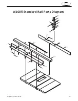
Страница 20: ...Shop Fox Classic Fence 17 26 W2005 Standard Rail Parts Diagram ...

Страница 21: ... 18 Shop Fox Classic Fence NOTE The W2006 is a combination of the W2005 Fence and the W2007 Legs and 7 Rails W2007 Leg and 7 Rail Parts Diagram ...

Страница 22: ...PN05 HEX NUT 1 4 20 35 X2005035 V CLAMP 36 X2005036 L BRACKET 37 X2005037 LOCKING PLATE 38 XPB26 HEX BOLT 1 4 20 X 1 1 2 39 XPW06 FLAT WASHER 1 4 40 XPN05 HEX NUT 1 4 20 41 XPB07 HEX BOLT 5 16 18 X 3 4 42 XPW07 FLAT WASHER 5 16 43 XPN02 HEX NUT 5 16 18 44 X2005044 MAGNET 45 XPS43 PHLP HD SCR 10 24 X 1 2 REF PART DESCRIPTION 6 X2007006 EXTENSION LEG 7 X2007007 FRONT RAIL TUBE 10 X2007010 REAR RAIL ...

Страница 23: ......

Страница 24: ......

Страница 25: ......

Отзывы: