


G9744Z Metal Cutting Bandsaw
-35-
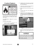
Note:
It is sometimes possible to flip the
blade inside out, in which case the blade will
be installed in the wrong direction. Check to
make sure the blade teeth are facing toward
the workpiece, as shown in
Figure 40
,
after
mounting on the bandsaw. Some blades will
have a directional arrow as a guide.
8.
Apply a light amount of tension to hold the
blade in place. Work your way around the
blade to adjust the position so the back of the
blade is against the flange of the wheels.
9.
Complete the blade change by following the
steps in
Blade Tension & Tracking
.
Figure 40.
Blade cutting direction.
������������
Blade Tension &
Tracking
Figure 41.
Blade tension indicator.
Blade Tension Indicator
NOTICE
Loosen blade tension at the end of each day
to prolong blade life.
To tension the blade on the bandsaw:
1.
Turn the blade tension handle clockwise to
tension the blade.
2.
Use the graduated scale on the blade tension
indicator
(
Figure 41
) to determine blade ten-
sion in PSI.
—For carbon blades, the blade tension should
be 20,000 PSI.
—For bi-metal blades, like the one supplied
with your machine, the blade should be
tensioned from 30,000 to 35,000 PSI.
Proper blade tension is essential to long blade
life, straight cuts, and efficient cutting. The Model
G9744Z features a blade tension indicator to
assist you with blade tensioning.
Two major signs that you do not have proper
blade tension are: 1) the blade stalls in the cut and
slips on the wheels, and 2) the blade frequently
breaks from being too tight.
Tracking Set Screw
3.
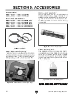
To fine tune blade tension, use a blade
tensioning gauge, like the one found in
SECTION 5: ACCESSORIES
on
Page 28
.
Please follow the instructions included with
your gauge and the blade manufacturer's
recommendations on blade tension.
Содержание G9744Z
Страница 2: ......
Страница 16: ...14 G9744Z Metal Cutting Bandsaw Hardware Recognition Chart...
Страница 42: ...40 G9744Z Metal Cutting Bandsaw Blade Guide Parts Breakdown...
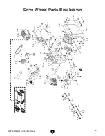
Страница 43: ...G9744Z Metal Cutting Bandsaw 41 Drive Wheel Parts Breakdown...
Страница 44: ...42 G9744Z Metal Cutting Bandsaw Main Parts Breakdown...
Страница 49: ......
Страница 50: ......
Страница 51: ......
Страница 52: ......