Grizzly G9744Z Скачать руководство пользователя страница 25

G9744Z Metal Cutting Bandsaw

-23-

Blade Selection

������

�����

�������

����������

�������

���������

�������

����������

���

����

�������

����������

���

����

�������

����������

���

����

�������

���������

������

���������

�������

���������

�����

���������

�������

���������

������

���������

�������

���������

�������

���������

�������

����������

���

����

�������

����������

�������

���������

��������

�����

����

����

�����

�����

������

�����

���������

�������

���������

�������

���������

�������

���������

�������

��������

���������������

���������������������������������

��������

��������

��������

����������

����������

����������

����������

�����

�����

�����

���������

����������

���������

����������

����������

����������

��������������

���������������

����

���������

�������

����������

���������

���������

���������

��������

���������

����������

��������

����������

�������������

����������

��

� �

��

��

��

��

�� ��

��

��

��

��

��

��

��

���

���

���

���

���

���

���

���

���

���

�������

�������

������

������

���

���

���

���

���

���

���

��

����

Material Width/Diameter

Material Shapes

Teeth Per Inch Variable Pitch Blades
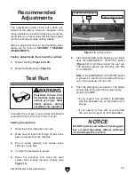
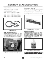
Figure 19.

 Model G9744Z blade selection and speed chart. 

The  Model  G9744Z  uses  129 

3

8

"  x  1"  bandsaw 

blades.

Selecting the right blade for the job depends on 
a variety of factors, such as the type of material 
being cut, hardness of the material, material shape 
machine capability, and operator technique.

The chart below is a basic starting point for choos-
ing blade type based on teeth per inch (TPI) for 
variable tooth pitch blades and for standard raker 
type  bi-metal  blades/HSS  blades.  However,  for 
exact  specifications  of  bandsaw  blades,  contact 
the blade manufacturer.

To select the correct blade TPI:

1.

  Measure  the  material  thickness.  This  mea-

surement  is  the  length  of  cut  taken  from 
where the tooth enters the workpiece, sweeps 
through, and exits the workpiece. 

2.

  Refer  to  the  "Material  Width/Diameter"  row 

of the blade selection chart in 

Figure 19

 and 

read across to find your workpiece thickness 
you need to cut.

3.

  Refer to the "Material Shapes" row and find 

the shape and material to be cut. 

4.

  In the applicable row, read across to the right 

and find the box where the row and column 
intersect.  Listed  in  the  box  is  the  minimum 
TPI recommended for the variable tooth pitch 
blades.

5.

  The "Cutting Speed Rate Recommendation" 

section of the charts offers guidelines for var-
ious metals, given in feet per minute (speed 
FPM) and meters per minute in parenthesis. 
Choose  the  speed  closest  to  the  number 
shown in the chart.

Содержание G9744Z

Страница 1: ...tting Bandsaw OWNER S MANUAL COPYRIGHT JULY 2006 BY GRIZZLY INDUSTRIAL INC WARNING NO PORTION OF THIS MANUAL MAY BE REPRODUCED IN ANY SHAPE OR FORM WITHOUT THE WRITTEN APPROVAL OF GRIZZLY INDUSTRIAL I...

Страница 2: ......

Страница 3: ...3 SETUP 12 Setup Safety 12 Items Needed for Setup 12 Unpacking 12 Inventory 13 Hardware Recognition Chart 14 Clean Up 15 Site Considerations 15 Moving Placing Base Unit 16 Mounting to Shop Floor 16 Sh...

Страница 4: ...eshooting 32 Blade Change 34 Blade Tension Tracking 35 Blade Guide Bearings 36 Squaring Blade to Table 37 Electrical Components 38 Model G9744Z 220V Wiring Diagram 39 Blade Guide Parts Breakdown 40 Dr...

Страница 5: ...set forth in this manual you can expect years of trouble free enjoyable operation and proof of Grizzly s com mitment to customer satisfaction We are pleased to provide this manual with the Model G9744...

Страница 6: ...lat Crate Content Machine Weight 860 lbs Length Width Height 69 x 29 1 2 x 47 1 2 in Electrical Switch Push Button ON OFF Switch Voltage 220V Cord Length 5 ft Cord Gauge 14 gauge Recommended Breaker S...

Страница 7: ...er Machined Cast Iron Body Construction Cast Iron Base Construction Pre Formed Steel Wheel Cover Construction Pre Formed Steel Paint Epoxy Other Wheel Size 13 in Blade Guides Upper Ball Bearing Blade...

Страница 8: ...entification A C B D E H I J K M A Blade Tension Handwheel B Lift Handle C Vise Handwheel D Coolant Drip Pan E Work Stop F Pulley Cover G Control Panel H Blade Guide Scale I Blade Guide Knob J Coolant...

Страница 9: ...n Note The bandsaw has an automatic shut off limit switch that turns the motor and coolant pump OFF at the bottom of the cut C START Button Turns the motor ON D Power Light When lit indicates that sys...

Страница 10: ...and can cause cancer and severe respiratory illnesses For Your Own Safety Read Instruction Manual Before Operating this Machine The purpose of safety symbols is to attract your attention to possible...

Страница 11: ...ories 16 MAKE SURE GUARDS ARE IN PLACE AND WORK CORRECTLY BEFORE USING MACHINERY Safety Instructions for Machinery 17 REMOVE ADJUSTING KEYS AND WRENCHES Make a habit of checking for keys and adjusting...

Страница 12: ...badly worn blade Inspect blades for cracks and missing teeth before each use 2 HAND PLACEMENT Never position fin gers or thumbs in line with the cut Hands could be crushed in vise or by falling machi...

Страница 13: ...ing circuit with one of higher amper age without consulting a quali ed electrician to ensure compliance with wiring codes If you are unsure about the wiring codes in your area or you plan to connect y...

Страница 14: ...This machine presents serious injury hazards to untrained users Read through this entire manu al to become familiar with the controls and opera tions before starting the machine Unpacking Setup Safety...

Страница 15: ...M12 1 75 x 50 Leveling 4 Hex Nuts M12 1 75 Leveling 4 Handwheel 1 Handwheel Handle 1 In the event that any nonproprietary parts are missing e g a nut or a washer we would be glad to replace them or fo...

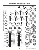
Страница 16: ...14 G9744Z Metal Cutting Bandsaw Hardware Recognition Chart...

Страница 17: ...ion during ship ment Remove this protective coating with a sol vent cleaner or citrus based degreaser such as Grizzly s G7895 Degreaser To clean thoroughly some parts may need to be removed For opti m...

Страница 18: ...have been included Bolting to Concrete Floors Lag shield anchors with lag bolts Figure 7 and anchor studs are two popular methods for anchoring an object to a concrete floor Mounting to Shop Floor NOT...

Страница 19: ...ipping bracket 1 Remove all four hex bolts shown in Figure 8 with a 12mm wrench The workstop is used when many cuts of the same length are needed see Figure 9 To setup the workstop 1 Position the work...

Страница 20: ...igure 11 Feed stop Jam Nut Feed Stop Feed Stop Depending on how the Model G9744Z was shipped it may be necessary to adjust the feed stop before the test run The blade should not make contact with any...

Страница 21: ...the bandsaw to power 5 Raise the bandsaw and close the feed control knob to keep the saw in place see Figure 12 Projectiles thrown from the machine could cause serious eye injury Wear safety glasses d...

Страница 22: ...projects Regardless of the content in this section Grizzly Industrial will not be held liable for accidents caused by lack of training Vise Always turn the saw OFF and allow the blade to come to a co...

Страница 23: ...le 4 Loosen the rear vise lock handle and swing the rear jaw until it reaches the 45 positive stop 5 Tighten the rear jaw and check the angle 6 If the angle is not at 45 loosen the vise jaw and adjust...

Страница 24: ...sting and drifting off of the cut line To adjust the rear blade guide arm Loosen the knob shown in Figure 17 and slide the rear blade guide as close to the workpiece as possible then tighten the knob...

Страница 25: ...t the blade manufacturer To select the correct blade TPI 1 Measure the material thickness This mea surement is the length of cut taken from where the tooth enters the workpiece sweeps through and exit...

Страница 26: ...feed rate is controlled by two knobs on the control panel Note If a lubricant is used on the cut the feed rate can be increased by approximately 15 To set the feed rate 1 Raise the bow to the highest...

Страница 27: ...trol valve Coolant Control Valve NOTICE Keep the tray chip screen clear so coolant can recycle to the pump reservoir NEVER operate the pump with the reservoir below the low mark or you will overheat t...

Страница 28: ...l cool and lubricate the blade and flush the chips away so they do not stick to the blade If the chips build up on the blade eventually they will bind and skid in the next cut breaking blade teeth and...

Страница 29: ...r Adjust the blade guides as close as possible to the workpiece to minimize side to side blade movement Use coolant when possible to increase blade life Operation Tips NOTICE Loosen blade tension at t...

Страница 30: ...G6436 1293 8 x 1 x 032 5 8 Variable Pitch G6437 1293 8 x 1 x 032 6 10 Variable Pitch G6438 1293 8 x 1 x 032 8 12 Variable Pitch H5405 Lenox Lube Tube Lenox Lube Tube is a stick lubricant designed to...

Страница 31: ...adio Headset Earmuffs Protect yourself comfortably with a pair of cush ioned earmuffs Especially important if you or employees operate for hours at a time H1302 H4977 H4979 G9256 6 Dial Caliper G9257...

Страница 32: ...bolts Damaged saw blade Worn or damaged wires Any other unsafe condition Clean after each use Proper blade tension Coolant level Coolant condition Monthly Check Lubricate vise screw Check gear box fl...

Страница 33: ...as needed to keep the pivot moving freely see Figure 35 The gearbox should be drained and refilled after the first 50 hours of use and then once every year Use a high quality ISO 68 or SAE 90 gear oi...

Страница 34: ...for broken wires or disconnected corroded connections and repair replace as necessary 9 Test repair replace Machine stalls or is under powered 1 Wrong blade for the workpiece material 2 Wrong workpie...

Страница 35: ...hard spots welds or scale is on the material 5 The blade is twisted 6 The blade is slipping on the wheels 1 Refer to Blade Speed on Page 24 and adjust as required 2 Refer to Blade Selection on Page 2...

Страница 36: ...lades to prevent cuts Figure 39 Installing the blade Figure 38 Opened upper blade guard Tension Handle Blade Guard Figure 37 Tension handle and blade Upper Blade Guard Screw Holes Blades should be cha...

Страница 37: ...o tension the blade on the bandsaw 1 Turn the blade tension handle clockwise to tension the blade 2 Use the graduated scale on the blade tension indicator Figure 41 to determine blade ten sion in PSI...

Страница 38: ...e blade guide bearings are adjusted at the fac tory but due to shipping and storage may need adjustment Use Figures 43 44 to guide you through the following steps To adjust the blade guide bearings 1...

Страница 39: ...e Figure 46 Bearing block pivot Lock Nut Set Screw Bearing Bracket Squaring Blade to Table This adjustment has been made at the factory and should not need to be adjusted under normal circumstances Ho...

Страница 40: ...s Figure 47 Limit switch SQ1 Figure 50 Pump motor wiring and capacitor M2 Figure 49 Control panel wiring Figure 48 Junction box M1 SB4 SB1 SB3 L Figure 51 G9744Z Contactor relay electrical box Fuse FU...

Страница 41: ...iring Diagram LEGEND M Motor KM1 Contactor Main Motor KM2 Pump Motor Relay KM1 Thermal Relay Main Motor L Indicator Lamp SB1 Emergency Stop Button SB3 Start Button SB4 Pump Motor Switch SQ1 Limit Swit...

Страница 42: ...40 G9744Z Metal Cutting Bandsaw Blade Guide Parts Breakdown...

Страница 43: ...G9744Z Metal Cutting Bandsaw 41 Drive Wheel Parts Breakdown...

Страница 44: ...42 G9744Z Metal Cutting Bandsaw Main Parts Breakdown...

Страница 45: ...X 50 90 P9744Z090 GIB 9 P9744Z009 BRACKET 91 P9744Z091 HOSE CLAMP 10 P9744Z010 SHAFT 92 PS05M PHLP HD SCR M5 8 X 8 41 PSB72M CAP SCREW M10 1 5 X 30 93 P9744Z093 ARM RIGHT 42 PLW06M LOCK WASHER 10MM 94...

Страница 46: ...46 P9744Z146 COLUMN RIGHT SUPPORT 231 PB26M HEX BOLT M8 1 25 X 30 147 PRP49M ROLL PIN 5 X 25 232 PW07 FLAT WASHER 5 16 148 PSB84M CAP SCREW M10 1 5 X 35 233 PN03M HEX NUT M8 1 25 149 PW04M FLAT WASHER...

Страница 47: ...296 PS05M PHLP HD SCR M5 8 X 8 348 PW06 FLAT WASHER 1 4 297 P9744Z297 DEGREE SCALE 349 PS07 PHLP HD SCR 1 4 20 X 3 8 298 PSS16M SET SCREW M8 1 25 X 10 350 P9744Z350 COUPLER PT 1 2 X 1 4 299 P9744Z299...

Страница 48: ...all be tried in the State of Washington County of Whatcom We shall in no event be liable for death injuries to persons or property or for incidental contingent special or consequential damages arising...

Страница 49: ......

Страница 50: ......

Страница 51: ......

Страница 52: ......

Отзывы: