-24-
G1495 Heavy-Duty
-24-
Faceplate turning is usually done on stock diam-
eters greater than 4'' and less than 8'' in length.
The maximum recommended stock diameter for
inboard turning is 14'' if less than 2'' thick. Reduce
the stock diameter if turning thicker stock.
Outboard turning can be done if the diameter is
greater than 14'', however we recommend a max-
imum diameter of 19'' and a maximum thickness
of 2'' due to the forces generated and the size of
the motor on the G1495. Outboard turning is
accomplished the same as described below,
except the adjustment of the tool rest is slightly
different.
Remember that centrifugal force increases along
with the diameter and mass of the workpiece. The
greater the centrifugal force, the greater the
potential for the workpiece to become dislodged
from the lathe mounting.
To mount stock for faceplate turning:
1. Remove the spur center using the knockout
bar. See Accessories Section, Spur Center
for more detail.
2. Attach stock to the faceplate. The faceplate
supplied is 6'' in diameter, however the hole
spacing provided will allow mounting of
stock down to 4''. If the stock is greater than
6'' and up to 14'' (for inboard turning), the
stock can still be mounted to this faceplate.
Stock can be attached using wood screws,
or if those will interfere with the finished
project, a backing block can be glued to the
back face of the stock to be used for attach-
ment. Ensure that the two mating surfaces
are flat and centered with each other. For
easy removal later, glue a piece of heavy
paper (e.g. a grocery bag) between the
stock and the backing block. Make sure
there is a strong bond before starting the
turning operation. After the turning is com-
plete, the two pieces can be separated with
a parting tool or a hammer and chisel to
break the glue joint.
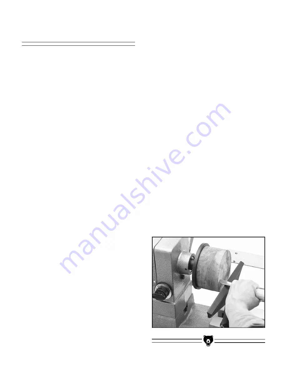
Faceplate Turning
Figure 27. Typical faceplate turning setup.
3. Mount the faceplate and the attached work-
piece to the headstock spindle. Install the
faceplate by threading it onto the spindle.
4. Move the tailstock to the far end of the bed
to assure it won’t interfere with the face-
plate turning operations. Remove the live
center from the tailstock to avoid injury.
5. Move the tool rest into position in front of
the mounted workpiece. The position
shown in Figure 27 would be for shaping
the face. The tool rest should be approxi-
mately
1
⁄
2
'' from the workpiece. When turn-
ing the outer edge the tool rest should be
moved so it is in close proximity to the edge
of the piece.
When faceplate turning, always remove material
using the scraping method. When making a
scraping cut the tool is held in a level position with
the tool edge contacting the surface of the work
even with, or slightly above, the horizontal center-
line. The tool rest should be slightly below the
centerline.
The gouge chisel should be used on faceplate
turning only when you have achieved a certain
proficiency with turning. Using the gouge can be
troublesome because there is a tendency of the
grain to grab the chisel, resulting in loss of con-
trol. When shaping narrow, inside surfaces, care
must be taken so that the chisel does not inad-
vertently catch on the surface.


