background image

-4-

Model G0733 (Mfg. Since 10/11)

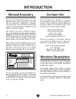
the following is a list of common definitions, terms and phrases used throughout this manual as they relate 
to this wood lathe and turning in general. Become familiar with these terms for assembling, adjusting or 
operating this machine. your safety is 

vERy important to us at grizzly! 

bed:  the  long,  rail-like  metal  base  to  which 

the  tailstock,  tool  base,  and  headstock  are 
attached.

chuck: a mechanical device that attaches to the 

spindle and holds the workpiece.

faceplate: the metal disc that threads onto the 

headstock spindle.

faceplate Turning:  turning  situation  in  which 

the grain of the turning stock is at right angles 
to the lathe bed axis. 

backing block: a sacrificial piece of wood glued 

to  the  base  of  the  workpiece  and  screwed  to 
the  faceplate.  often  used  to  prevent  mount-
ing  marks  from  appearing  on  the  completed 
workpiece. 

Headstock:  the  cast  metal  box  to  which  the 

motor  is  attached  and  contains  the  spindle, 
bearings, belts, and electrical components for 
operating the lathe. 

index head: the  mechanism  that  allows  the 

headstock  spindle  to  be  locked  at  specific 
intervals for layout or other auxiliary tasks. 

Offset Turning: a turning situation where the cen-

ter of the workpiece is offset at various stages 
of the work to produce different shapes. 

Outboard Turning:  turning  of  workpiece  with 

the  headstock  situated  at  the  far  end  of  the 
lathe so the work done is not over the bed of 
the lathe.

Roughing Out: taking stock from square billet to 

round blank. 

Spindle:  this  term  has  two  meanings.  First,  it 

refers  to  the  threaded  shaft  in  the  headstock 
to  which  the  faceplate  is  attached.  second,  it 
refers to any work that is spindle-turned.

Spindle-Turning:  Work  performed  where  the 

grain and length of the workpiece are parallel 
to the axis of the bed. 

Swing:  the  capacity  of  the  lathe,  measured 

by  doubling  the  distance  from  the  bed  to  the 
spindle center. 

Tailstock: the metal component at the opposite 

end of the bed from the headstock containing a 
quill and live or dead centers. it maintains pres-
sure on the spindle-turned workpiece. 

Tool base:  the  movable  metal  fixture  attached 

to the bed upon which the tool rest is fixed. 

Tool Rest: the adjustable metal arm upon which 

the tool rest during a turning operation. 

Way: one of the metal rails that make up the bed 

of the lathe. 

Glossary Of Terms

Содержание G0733

Страница 1: ...dels manufactured since 10 11 Copyright NovemBER 2011 By Grizzly Industrial Inc REVISED APRIL 2013 ST Warning No portion of this manual may be reproduced in any shape Or form without the written approval of Grizzly Industrial inc KN14454 printed IN China ...

Страница 2: ...ng grinding tool integrity and the usage of personal protective equipment The manufacturer will not be held liable for injury or property damage from negligence improper training machine modifications or misuse Some dust created by power sanding sawing grinding drilling and other construction activities contains chemicals known to the State of California to cause cancer birth defects or other repr...

Страница 3: ...lstock 22 Adjusting Tool Rest 22 Installing Removing Headstock Center 23 Installing the Headstock Center 23 Removing the Headstock Center 23 Installing Removing Tailstock Center 24 Installing the Tailstock Center 24 Removing the Headstock Center 24 Installing Faceplate 25 Changing Speed Ranges 25 Indexing 27 Spindle Turning 27 Spindle Turning Tips 29 Faceplate Turning 29 Mounting the Workpiece ont...

Страница 4: ...on our website at www grizzly com Any updates to your model of machine will be reflected in these documents as soon as they are complete Manufacture Date of Your Machine Contact Info We stand behind our machines If you have any questions or need help use the information below to contact us Before contacting please get the serial number and manufacture date of your machine This will help us help yo...

Страница 5: ...ation Motor Belt Tension Lever Control Panel Headstock Faceplate Tool Rest Tailstock Casting Quill Lock Lever Quill Stand Leg Stand Leg Storage Basket Bed Belt Access Cover Spindle RPM Readout Speed Control Knob Spindle Direction Switch ON OFF Switch w Emergency STOP Button Tool Rest Base Spindle Indexing Holes Tool Rest Base Lock Lever Handwheel Tool Rest Lock Handle Belt Tension Lock Lever Tails...

Страница 6: ...tock spindle to be locked at specific intervals for layout or other auxiliary tasks Offset Turning A turning situation where the cen ter of the workpiece is offset at various stages of the work to produce different shapes Outboard Turning Turning of workpiece with the headstock situated at the far end of the lathe so the work done is not over the bed of the lathe Roughing Out Taking stock from squ...

Страница 7: ... x 22 in Must Ship Upright N A Electrical Power Requirement 220V Single Phase 60 Hz Prewired Voltage 220V Full Load Current Rating 5 3A Minimum Circuit Size 15A Connection Type Cord Plug Power Cord Included Yes Power Cord Length 9 1 2 ft Power Cord Gauge 14 AWG Plug Included Yes Included Plug Type 6 15 Switch Type ON OFF Push Button Switch w Safety Cover Inverter Type Delta VFD M Inverter Size 2 H...

Страница 8: ...Cast Iron Frame Cast Iron Stand Cast Iron Base Cast Iron Headstock Cast Iron Tailstock Cast Iron Paint Enamel Other Related Information Faceplate Size 6 in Other Specifications Country Of Origin China Warranty 1 Year Approximate Assembly Setup Time 1 Hour Serial Number Location ID Label on Front of Bed ISO 9001 Factory No CSA Certified No Features 14 wide tool rest with post size of 2 1 4 H x 1 Ø ...

Страница 9: ...oof DANGEROUS ENVIRONMENTS Do not use machinery in areas that are wet cluttered or have poor lighting Operating machinery in these areas greatly increases the risk of accidents and injury MENTAL ALERTNESS REQUIRED Full mental alertness is required for safe operation of machin ery Never operate under the influence of drugs or alcohol when tired or when distracted For Your Own Safety Read Instructio...

Страница 10: ...oving parts or flying debris Make sure they are properly installed undamaged and working correctly FORCING MAChINERY Do not force machine It will do the job safer and better at the rate for which it was designed NEVER sTANd ON MAChINE Serious injury may occur if machine is tipped or if the cutting tool is unintentionally contacted sTABLE MAChINE Unexpected movement dur ing operation greatly increa...

Страница 11: ... t fly apart during operation ADJUSTMENTS MAINTENANCE Make sure your wood lathe is turned OFF disconnected from its power source and all moving parts have come to a complete stop before starting any inspection adjustment or maintenance procedure STOPPING LATHE DO NOT stop the lathe by using your hand against the workpiece Allow the lathe to stop on its own AVOIDING ENTANGLEMENT Keep long hair and ...

Страница 12: ...or fire may result especially if connected to an undersized circuit To reduce the risk of these hazards avoid over loading the machine during operation and make sure it is connected to a power supply circuit that meets the requirements in the following section For your own safety and protection of property consult an electrician if you are unsure about wiring practices or electrical codes in your ...

Страница 13: ... longer and the gauge size gets smaller higher gauge numbers indicate smaller sizes Any extension cord used with this machine must contain a ground wire match the required plug and receptacle and meet the following require ments Minimum Gauge Size 14 AWG Maximum Length Shorter is Better 50 ft Grounding Requirements This machine MUST be grounded In the event of certain malfunctions or breakdowns gr...

Страница 14: ...achine and inspect it If you discover any damage please call us immediately at 570 546 9663 for advice Save the containers and all packing materials for possible inspection by the carrier or its agent Otherwise filing a freight claim can be difficult When you are completely satisfied with the condi tion of your shipment inventory the contents Unpacking SUFFOCATION HAZARD Keep children and pets awa...

Страница 15: ... Ea I Knockout Tool 1 J Storage Basket 1 K Hardware not shown Cap Screws M8 1 25 x 35 10 Lock Washers 8mm 10 Hex Nuts M8 1 25 2 If any nonproprietary parts are missing e g a nut or a washer we will gladly replace them or for the sake of expediency replacements can be obtained at your local hardware store B C D E F G H J NOTICE Some hardware fasteners on the inventory list may arrive pre installed ...

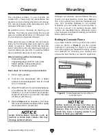
Страница 16: ...hine is operated is important for safe operation and lon gevity of machine components For best results operate this machine in a dry environment that is free from excessive moisture hazardous chemi cals airborne abrasives or extreme conditions Extreme conditions for this type of machinery are generally those where the ambient temperature range exceeds 41 104 F the relative humidity range exceeds 2...

Страница 17: ...uring shipment and storage This rust preventative works extremely well but it will take a little time to clean Be patient and do a thorough job cleaning your machine The time you spend doing this now will give you a better appreciation for the proper care of your machine s unpainted surfaces There are many ways to remove this rust preven tative but the following steps work well in a wide variety o...

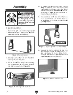
Страница 18: ...achine feet see Figure 11 To assemble your lathe 1 Position the right and left stand legs upright approximately 573 4 apart and get them reasonably aligned see Figure 9 2 Carefully position the lathe onto the stands and align the mounting holes 3 Secure the lathe assembly to the stand legs with 8 M8 1 25 x 35 cap screws and 8mm lock washers as shown in Figure 10 Figure 10 Securing lathe assembly x...

Страница 19: ...nuts as shown in Figure 14 Figure 14 Attaching basket to leg Leg Basket Power Connection After you have completed all previous setup instructions and circuit requirements the machine is ready to be connected to the power supply To avoid unexpected startups or property dam age use the following steps whenever connecting or disconnecting the machine Connecting Power Figure 15 Connecting power 1 Turn...

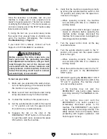
Страница 20: ... correcting potential problems 7 Turn the speed control knob all the way counterclockwise 8 Turn the spindle direction switch to the L position and slowly turn the speed control knob to the right When operating correctly the machine runs smoothly with little or no vibration or rubbing noises 9 Move the spindle direction switch to the O position and push in the EMERGENCY STOP button 10 WITHOUT open...

Страница 21: ... components discussed later in this manual are easier to understand Due to the generic nature of this overview it is not intended to be an instructional guide To learn more about specific operations read this entire manual and seek additional training from expe rienced machine operators and do additional research outside of this manual by reading how to books trade magazines or websites Damage to ...

Страница 22: ...ip tions of the controls is useful when reading this OPERATIONS section A Figure 17 Control panel and RPM Readout B C D 7 Verifies the pulley ratio is set for the appro priate speed range for the operation type of wood and size of workpiece installed 8 Verifies the spindle direction switch is in the O position and the spindle speed dial is turned all the way counterclockwise so the spindle does no...

Страница 23: ... Lever Stock Inspection Requirements Some workpieces are not safe to turn or may require modification before they are safe to turn Before turning a workpiece inspect all workpieces for the following Workpiece Type This machine is intended for turning natural wood products Never attempt to turn any composite wood materials plastics metal stone or rubber workpieces turning these materials can lead t...

Страница 24: ... being ejected at high speed Tailstock Lock Lever Adjusting Tool Rest The tool rest assembly on the Model G0733 has two adjustable components to provide the safest and most stable position when operating the lathe The tool rest base adjusts in the same manner as the headstock and tailstock The tool rest pivots and may be adjusted vertically in the tool rest base To position the tool rest assembly ...

Страница 25: ...and spindle are free of debris and oily sub stances before inserting the center to ensure a good fit and reduce runout 3 Insert the tapered end of the center into the spindle and push it in with a quick firm motion as shown in Figure 22 Headstock Center Removing the Headstock Center 1 DISCONNECT LATHE FROM POWER 2 Hold a clean rag under the spindle or wear a glove to catch the center when you remo...

Страница 26: ...ter into tailstock quill Quill Quill Lock Handle Handwheel Figure 25 Quill lock handle aligned with quill keyway Quill Lock Handle Quill Keyway 5 Make sure the center of the quill lock handle is aligned with the quill keyway to ensure that the tailstock center and quill will not freely rotate under load see Figure 25 6 Secure the quill in place by re tightening the quill lock handle Removing the H...

Страница 27: ...ghten the two set screws along the inside diameter of the faceplate to secure it to the spindle see Figure 26 Figure 26 Locking spindle with indexing pin and faceplate set screw location Faceplate Set Screw 1 of 2 Changing Speed Ranges The Model G0733 has pulley belt configuration provided two speed ranges see Figure 27 Note To maximize spindle torque use the low spindle speed range for spindle sp...

Страница 28: ...ng handle and tension lock handle Belt Tensioning Handle Belt Tension Lock Handle 5 Reach into the belt access cavity and roll the belt onto the desired set of pulleys as shown in Figure 31 6 Loosen the belt tension lock handle and lower the motor 7 Apply downward pressure on the belt tension ing handle to properly tension the drive belt then re tighten the belt tension lock handle Note When prope...

Страница 29: ...4 Indexing pin and indexing holes Figure 33 Model G0733 indexing configuration Indexing Pin 4 Outer Indexes Faceplate 12 Inner Indexes Spindle Spindle Turning Spindle turning is the operation performed when a workpiece is mounted between the headstock and the tailstock as shown in Figure 35 Figure 35 Typical spindle turning operation To set up a spindle turning operation 1 Find the center point of...

Страница 30: ...arate during installation 8 Install the live center into the tailstock quill and tighten the quill lock handle to lock the quill in position refer to Page 24 for addi tional instructions 9 Slide the tailstock toward the workpiece until the point of the live center touches the workpiece center mark then lock the tailstock in this position 10 Loosen the quill lock handle and rotate the tailstock han...

Страница 31: ...eable lathe users Damage to your eyes and lungs could result from using this machine without proper pro tective gear Always wear a face shield and respirator when operating this machine Faceplate Turning Faceplate turning is when a workpiece is mounted to the faceplate which is then mounted to the headstock spindle as shown in Figure 39 This type of turning is usually done with open faced workpiec...

Страница 32: ...k the center of both the workpiece and backing block 3 Drill a 1 4 hole through the center of the backing block 4 Look through the hole in the backing block to line up the center with the workpiece and glue and clamp the backing block to the workpiece Note Allow the glue to cure according to the manufacturer s instructions 5 Follow Steps 1 3 under Mounting the Workpiece onto the Faceplate see Page...

Страница 33: ...ng opera tions Failure to do so could cause the tool to be pulled out of the operator s control and ejected at high speed Figure 42 Lathe prepared for outboard turning Sanding Finishing After the turning operations are complete the workpiece can be sanded and finished before removing it from the lathe as shown in Figure 43 Figure 43 Typical sanding operation Note Whenever sanding or finishing move...

Страница 34: ...d with one side higher than the other usually at an angle of 20 40 Figure 45 Example of a skew chisel Scrapers Typically used where access for other tools is limited such as hollowing oper ations This is a flat double ground tool that comes in a variety of profiles round nose spear point square nose etc to match many different contours Figure 46 Example of a round nose scraper Parting Tools Used f...

Страница 35: ...h speed steel construction for long life and dependable use Below are just some of the options available with this system T21644 16 Sovereign System w Collets T21645 22 Sovereign System w Collets T21648 Sovereign 3 8 Collets T21649 Sovereign 1 2 Collets T21654 1 4 Bowl Gouge T21655 3 8 Bowl Gouge T21656 1 2 Bowl Gouge T21660 3 4 Bowl Gouge Figure 48 Sovereign 16 and 22 handles T23311 Shop Fox 5 pc...

Страница 36: ...rmination of external measurements Ideal for physically transferring dimensions from originals Five different sizes allow you to match the best caliper for your shop needs Figure 52 Models H5884 H5887 Pencil Dividers H5884 8 Pencil Divider H5885 10 Pencil Divider H5886 12 Pencil Divider H5887 16 Pencil Divider Transfer precise distances for highly accurate layouts Bisect angles for precise angle m...

Страница 37: ...one of these Figure 59 T10117 Big Mouth Dust Hood Recommended Metal Protectants G5562 SLIPIT 1 Qt Gel G5563 SLIPIT 12 oz Spray G2871 Boeshield T 9 12 oz Spray G2870 Boeshield T 9 4 oz Spray H3788 G96 Gun Treatment 12 oz Spray H3789 G96 Gun Treatment 4 5 oz Spray Figure 58 Recommended products for protect ing unpainted cast iron steel part on machinery G5683 Magnetic Base Light Light up your work j...

Страница 38: ...ebris or oily substances from the inside of the spindle and quill Cleaning Protect the unpainted cast iron lathe bed by using a lightly oiled rag and wiping it clean after every use this ensures moisture from wood dust does not remain on the bare metal surfaces Keep your lathe bed rust free with regular applica tions of products like G96 Gun Treatment SLIPIT or Boeshield T 9 Lathe Bed Lubrication ...

Страница 39: ... and chisels reduce the feed rate depth of cut 2 Decrease feed rate cutting speed 3 Replace bad belt and re tension see Page 39 4 Correct motor wiring connections 5 Replace loose pulley 6 Test by rotating shaft rotational grinding loose shaft requires bearing replacement 7 Clean off motor let cool and reduce workload 8 Test repair replace Machine has vibration or noisy operation without workpiece ...

Страница 40: ...belt see Page 39 8 Replace spindle bearings Chisels grab or dig into workpiece 1 Tool rest set too low 2 Tool rest set too far from workpiece 3 Wrong chisel tool being used 4 Chisel tool dull 1 Set tool rest higher See Page 22 for how to prop erly set the tool rest height 2 Move the tool rest closer to the workpiece See Page 22 for the proper workpiece tool rest clear ance 3 Use the correct chisel...

Страница 41: ... the new belt by reversing Step 5 7 Apply downward pressure on the belt tension ing handle to properly tension the drive belt then re tighten the belt tension lock handle Note When properly tensioned the belt should deflect about 1 8 when moderate pres sure is applied to the belt mid way between the upper and lower pulley as illustrated in Figure 32 8 Ensure the belt ribs are fully seated in the p...

Страница 42: ...eck all wires dis connected or connected during any wiring task to ensure tight connections CIRCUIT REQUIREMENTS You MUST follow the requirements at the beginning of this man ual when connecting your machine to a power source WIRE COMPONENT DAMAGE Damaged wires or components increase the risk of serious per sonal injury fire or machine damage If you notice that any wires or components are damaged ...

Страница 43: ...er Control Ground Hot Hot 220 VAC Single Phase 6 15 Plug As Recommended DELTA POWER INVERTER 1 5 Kw 220V 1 3 Phase 23 24 13 14 Brake B1 B2 R L1 S L2 T L3 VFD M RPM Sensor RPM Readout Board 080307 U1 V1 W2 U2 V2 W1 GND GND 1 3 7 11 5 9 4 2 6 10 8 12 Spindle Direction Switch KEDU ZH A EN61058 Both sides shown V2 U2 V1 U1 W2 W1 RC RA M0 M1 M2 M3 M4 M5 GND AFM AC1 10V AVI GND MCM M01 RB ...

Страница 44: ... 42 Model G0733 Mfg Since 10 11 READ ELECTRICAL SAFETY ON PAGE 40 Wiring Components Figure 63 Inverter box and motor box locations Figure 60 RPM readout display board and control panel wiring ...

Страница 45: ...698021 HANDWHEEL HANDLE 6 PW04M FLAT WASHER 10MM 22 P0698022 HANDWHEEL 7 PCAP84M CAP SCREW M10 1 5 X 35 23 P0698023 TAILSTOCK CASTING 8 PR08M EXT RETAINING RING 19MM 24 PRP30M ROLL PIN 5 X 50 9 PCAP50M CAP SCREW M5 8 X 10 25 PR08M EXT RETAINING RING 19MM 10 P0698010 TOOL REST BASE PLATE 26 P0698026 TAILSTOCK CLAMP BOLT 11 P0698011 TOOL REST BASE 27 P0698027 ECCENTRIC BUSHING 19 X 26 X 33 12 P06980...

Страница 46: ... 35 36 37 38 39 40 41 42 43 44 45 110 111 113 46 47 48 49 53 54 55 56 57 57 1 57 2 57 3 57 6 57 7 57 5 57 4 57 8 57 9 57 10 97 58 59 60 61 62 63 64 65 66 67 68 69 70 71 73 74 75 76 80 81 83 84 85 86 112 88 89 87 90 92 93 94 95 96 100 99 101 103 104 105 106 107 108 ...

Страница 47: ...KEDU ZH A 54 P0698054 HEADSTOCK LOCK LEVER 89 P0698089 PANEL COVER 55 P0698055 POWER CORD 14G 3W 72 6 15 90 PS38M PHLP HD SCR M4 7 X 10 56 P0698056 STRAIGHT STRAIN RELIEF 3 8 92 P0733092 RPM DIGITAL READOUT W SENSOR 57 P0733057 MOTOR 2HP 220V 3PH 93 P0698093 SPINDLE LOCK TOOL 57 1 P0733057 1 MOTOR FAN COVER 94 P0698094 SWITCH BOX 57 2 P0733057 2 MOTOR FAN 95 PR08M EXT RETAINING RING 19MM 57 3 P073...

Страница 48: ...BEL 12D READ MANUAL LABEL 204 P0733204 MACHINE ID LABEL 209 PPAINT 11 GRIZZLY PUTTY PAINT 205 PPAINT 1 GRIZZLY GREEN PAINT 210 P0733210 NOTICE LABEL 201 202 203 204 206 207 208 205 209 210 Safety labels help reduce the risk of serious injury caused by machine hazards If any label comes off or becomes unreadable the owner of this machine MUST replace it in the original location before resuming oper...

Страница 49: ... metalworker ____ 0 2 Years ____ 2 8 Years ____ 8 20 Years ____20 Years 6 How many of your machines or tools are Grizzly ____ 0 2 ____ 3 5 ____ 6 9 ____10 7 Do you think your machine represents a good value _____Yes _____No 8 Would you recommend Grizzly Industrial to a friend _____Yes _____No 9 Would you allow us to use your name as a reference for Grizzly customers in your area Note We never use ...

Страница 50: ...D LINE FOLD ALONG DOTTED LINE GRIZZLY INDUSTRIAL INC P O BOX 2069 BELLINGHAM WA 98227 2069 Place Stamp Here Name_______________________________ Street_______________________________ City______________State______Zip______ Send a Grizzly Catalog to a friend ...

Страница 51: ...e tried in the State of Washington County of Whatcom We shall in no event be liable for death injuries to persons or property or for incidental contingent special or consequential damages arising from the use of our products To take advantage of this warranty contact us by mail or phone and give us all the details We will then issue you a Return Number which must be clearly posted on the outside a...

Страница 52: ......

Отзывы: