-22-
Model G0733 (Mfg. Since 10/11)
Adjusting Tailstock
the tailstock adjusts in the same manner as the
headstock.
To position the tailstock along the length of
the bed:
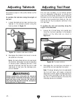
1. loosen the tailstock lock lever and move the
tailstock to the desired position along the
bed, as shown in
figure 19.
figure 19. tailstock lock lever location.
2. re-engage the tailstock lock lever to secure
the tailstock to the bed.
Note:
The large clamping hex nut underneath
the tailstock will require occasional adjusting
to ensure proper clamping pressure of the
tailstock to the bed. Turn this hex nut in small
increments to fine tune the clamping pres-
sure as needed.
Always operate the lathe with the tailstock
firmly locked to the bed. Otherwise, serious
personal injury may occur by the tailstock
moving during operation and the workpiece
being ejected at high speed.
tailstock lock
lever
Adjusting Tool Rest
the tool rest assembly on the model g0733
has two adjustable components, to provide the
safest and most stable position when operating
the lathe. the tool rest base adjusts in the same
manner as the headstock and tailstock. the tool
rest pivots and may be adjusted vertically in the
tool rest base.
To position the tool rest assembly along the
length of the lathe bed:
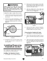
1. loosen the tool rest base lock handle and
move the tool rest assembly to the desired
position on the lathe bed, as shown in
figure 20.
tool rest
2. re-engage the tool rest base lock lever to
secure the tool rest assembly in position.
Note:
The large clamping hex nut underneath
the tool rest base will require occasional
adjusting to ensure proper clamping pressure
of the tool rest assembly to the bed. Turn this
hex nut in small increments to fine tune the
clamping pressure as needed.
figure 20. tool rest controls.
tool rest
tool rest
lock handle
tool rest Base
lock lever
Содержание G0733
Страница 52: ......


