


Model G0700 (Mfd. Since 5/14)
-63-
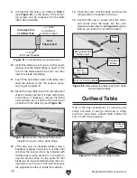
The table is calibrated at the factory, but can be
adjusted slightly if it is not parallel to the blade.
Tools Needed:
Qty
Felt Tip Pen ........................................................1
90° Square .........................................................1
Precise Measuring Tool ......................................1
Wrench 17mm ....................................................1
Hex Wrench 5mm ...............................................1
To adjust the sliding table parallel with the
main blade:
1. DISCONNECT SAW FROM POWER!
2. Move the blade tilt to 0˚ (blade 90˚ to table),
and raise the main blade up to the maximum
height.
3. Mark one of the blade teeth with a felt tip pen.
This will be your reference point when taking
measuring points, so you take them in the
same location each time.
4. Move the sliding table all the way back, and
measure the distance "A" in
Figure 111,
between the marked tooth and the edge of
the miter slot.
6. Note the difference between the two posi-
tions.
— If the gap is the same on both sides or the
difference is 0.004" or less, no adjustments
to the table parallelism need to be made.
— If the difference is greater than 0.004",
then the sliding table parallelism must be
adjusted. Proceed to
Step 7.
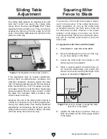
7. Loosen the sliding table mounting nuts (see
Figure 112) at both mounting locations.
Sliding Table Parallel
Adjustment
5. Rotate the blade 180°, move the sliding table
all the way forward, and measure the dis-
tance between "B" in
Figure 111.
8. At the side of the table that needs to move,
loosen the hex nut on the parallel adjustment
screw.
9. Slowly rotate the parallel adjustment screw
(see
Figure 112) as necessary to move the
table. If you move the adjustment screw away
from the table, then push the table against
the screw before proceeding.
10. Tighten the hex nut on the parallel adjust-
ment screw to secure it in place, then tighten
the table mounting nuts. Repeat
Steps 4–6
as necessary until the sliding table is parallel
with the blade.
Figure 112. Table parallelism adjustment
controls.
Parallel
Adjustment Screw
Table
Mounting Nuts
Figure 111. Measuring distance between table
and blade.
Marked Tooth
B
Marked Tooth
Blade
Miter Slot
A
Содержание G0700
Страница 17: ...Model G0700 Mfd Since 5 14 15 Hardware Recognition Chart...
Страница 85: ......


